TL;DR: A speed limiter that’s not engaging almost always comes back to one of five root causes: no power or a bad ground, a blown fuse or failed relay, CAN bus communication problems, a missing or incorrect speed signal, or firmware/calibration issues. Work through those in a structured order instead of guessing or throwing parts at it.
Key Takeaways
- Most “speed limiter not engaging” complaints trace back to basics: power supply, ground integrity, CAN bus communication, speed signal quality, or calibration faults. Don’t skip the fundamentals.
- A quick 5‑point check (fuse, relay, ground, CAN LED, speed signal, error codes) will solve the majority of field issues if you actually test, not just look.
- You’ll save hours if you have proper tools on hand: a reliable multimeter, a decent OBD‑II scanner, and when possible a CAN bus analyzer and access to the firmware diagnostic log.
- The speed governor diagnostic LED is one of the most underused tools. Its color and flash pattern often tell you in seconds whether you’re fighting power, CAN, or internal logic faults.
- Intermittent engagement failures are a different animal. They usually need data logging of voltage, CAN traffic, speed, GPS, vibration, and temperature over time, not quick spot checks in the bay.
- Once wiring, power, and calibration are proven solid, repeat non‑engagement usually means the module itself is failing. At that point, replacement if unfixable is often cheaper than endless troubleshooting.
- Drivers should always log the failure and report non‑engagement. That’s not just for the techs; it can matter for safety investigations, legal exposure, and insurance claims.
What Is a Speed Limiter and “Not Engaging” Condition?
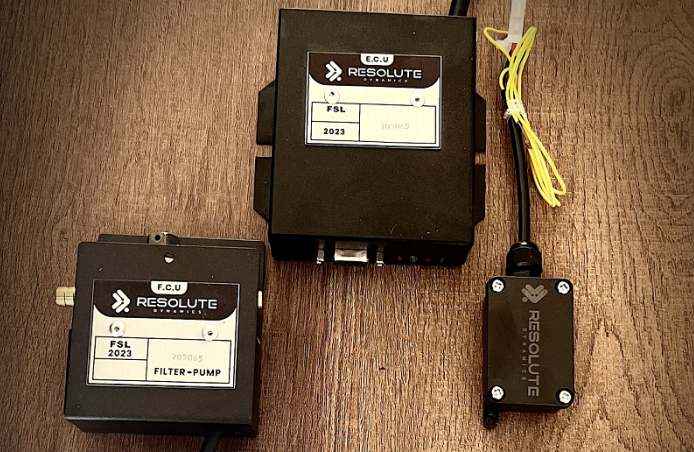
Speed limiter (speed governor): An electronic control module that keeps an eye on vehicle speed and stops it from going past a set limit. It usually does that by pulling back throttle command, adjusting torque requests, or sending limit instructions over the CAN bus to the ECU. Think of it as an electronic ceiling on road speed.
“Not engaging” condition: The vehicle blows right past the programmed limit without any governing, or the limiter never flips from its “armed/monitoring” state into “active” even though the conditions look correct. For example, the truck hits the target speed in the correct gear with no lockout switches active, but you never feel the limiter step in.
Speed limiter not working vs. not engaging: “Not working” can cover anything from no power, stuck in fault, wrong limit, or a dead sensor. “Not engaging” is more specific. It means the module is awake and watching but fails to activate governing when the speed criteria are met.
Speed Limiter Not Engaging: Start With These 5 Quick Checks
If a speed limiter is not engaging, start with the basics before you reach for the exotic theories. In the real world, five quick checks catch most issues: verify power supply at the module, confirm a solid ground connection, look at the CAN bus communication LED, validate the speed signal source, and review diagnostic LED patterns and error codes.
Do these first, every time. Those five quick checks fix well over 80% of “why is my speed limiter not limiting?” complaints on the first visit if you perform them properly and write down what you find.
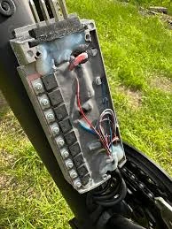
1. Power Supply Verification (Fuse, Relay, Voltage)
If the governor isn’t powered correctly, it won’t engage. Simple as that. Grab a multimeter, the fuse panel layout, and the wiring diagram for the limiter circuit.
- Identify the governor fuse and relay: Use the service manual or fuse panel map to find the correct cavity and rating. Don’t assume the last installer used the right slot just because it “looks about right.”
- Fuse check: Pull the fuse, check for heat discoloration, hairline cracks, or melted plastic, then test continuity with the meter. Replace anything that looks tired, not just totally blown.
- Governor relay: If there’s an identical relay in the panel, swap it and see if the symptom changes. You can also bench test the relay for coil resistance and contact function, but a quick swap is usually faster in the field.
- Voltage at module: With the ignition in the correct position for limiter operation, back‑probe the power feed at the governor connector. You should see stable system voltage, typically 12–14 V DC on a light‑vehicle system. Watch it while cycling loads like headlights or blower. If it dips or drops out, that’s a clue.
Write down the numbers. If voltage is low or flickers when you wiggle the harness, you’re likely dealing with a corroded splice, damaged feed, or an ignition source that’s not as “key hot” as the wiring diagram claimed.
2. Ground Fault Check (Resistance in Ohms)
A bad ground can make an otherwise good speed limiter look stone dead or cause it to reset right when it should engage. I see this more than anything else on retrofit installs.
- With ignition off, unplug the module and measure resistance between the governor ground pin and a clean chassis ground point.
- You want something very close to 0 Ω. In practice anything under about 0.3 Ω is usually fine on a short, clean ground. Higher readings scream “corrosion, loose bolt, or ground lug on painted metal.”
- Do a wiggle test. Move the harness, tug gently on the ground strap, flex the loom while watching the meter. If resistance spikes when you move something, you just found an intermittent ground.
3. Speed Governor Diagnostic LED Status
Most decent modern governors have a speed governor diagnostic LED either on the module itself or on a pigtail. That little light can save you a huge amount of guesswork if you know what it’s telling you.
- Green steady: Internal self‑test passed, power and ground look good, and the unit is armed and ready to govern. If it’s not engaging in this state, you’re probably dealing with speed input or calibration, not raw power.
- Red flash: Active fault. Flash counts usually map to a specific error code or category, like missing speed, CAN fault, or internal memory error. Check the manual or the OEM code chart.
- Amber (yellow): Warning state. Often means an abnormal input, like speed present but not plausible, configuration out of range, or a soft fault that hasn’t shut the unit down yet.
- Off: With ignition on, an unlit LED means no power, dead ground, or a module that’s failed internally and never even started its self‑test.
Always pair the LED’s flash pattern with the official code list. Many governors can show a CAN handshake failure, invalid configuration, or watchdog reset history just from how that LED blinks. Don’t ignore it because “the truck still drives.”
4. CAN Bus Communication Check
On systems that talk over CAN (J1939, ISO 15765, etc.), a broken conversation can stop the limiter from ever engaging even though the module looks powered and “alive.” It might be waiting for speed or torque limit commands that never arrive.
- Check the CAN high and CAN low twisted pair for damage, wrong splices, or crushed sections. Make sure termination resistors are present where they should be.
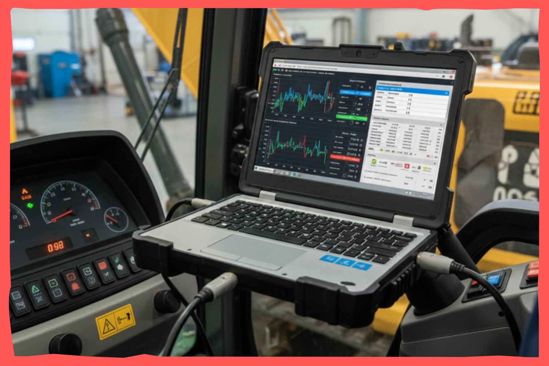
- Use an OBD‑II scanner or heavy‑duty scan tool to see if other nodes like the dash, ECU, or ABS are flagging network faults or reporting “no communication” with any module.
- If you’ve got access, hook up a CAN bus analyzer and watch for the expected message rate on the speed signal and limiter messages. Many systems broadcast speed at 10–50 Hz. If speed packets disappear or the limiter never transmits, that’s your lead.
- Look out for “bus off” events, dominant shorts to ground or battery, or the wrong baud rate on an aftermarket add‑on that someone spliced in last year.
If the CAN traffic is missing, noisy, or corrupt, you’ll chase your tail if you blame the limiter first. Sort the network. If you suspect the limiter and ECU or cruise are fighting over control, see this related guide: .
5. Speed Signal Source Verification & Error Code Readout
The limiter can’t make good decisions without an honest speed signal. A dead, noisy, or mis‑scaled speed feed is one of the most common reasons a governor never steps in.
- Figure out how this specific system gets speed. That might be a dedicated speed signal wire from a VSS, a CAN‑derived speed message, or in some fleet systems, a GPS‑based feed from a telematics unit.
- Use a scanner or oscilloscope to measure the expected frequency (Hz per km/h) at a known road speed. For example, at 60 km/h you should see a steady, predictable pulse rate on a VSS wire.
- Check continuity and insulation on the speed signal wire from sensor to module. Shorts to ground, shorts between twisted pairs, or rodent damage near the frame rails are all common in real fleets.
Then grab an OBD‑II scanner or the manufacturer’s app and pull the error code readout. On governors that support tools like Resolute Dynamics diagnostic mode, you can usually see clear flags for missing speed input, out‑of‑range calibration parameters, or internal errors. Those codes often narrow things down faster than guessing by feel.
Quick Diagnostic Checks Summary Table
This table gives you a quick “what good looks like” snapshot for the 5 starting checks. Use it as a bench reference while you test.
| Check | Attribute | Expected Value / Note |
|---|---|---|
| Power supply | Fuse / relay / voltage | Fuse intact, relay activates or passes continuity, and a steady 12–14 V measured at the module with ignition in the correct position |
| Ground | Resistance (ohms) | Typically <0.3 Ω from module ground pin to a clean chassis ground point, stable during wiggle test |
| CAN LED | Status meaning | Green steady indicates normal power and internal status; red or amber points to communication issues or internal faults that need code lookup |
| Speed signal | Expected vs actual | Pulse frequency or CAN parameter rises smoothly with road speed and remains stable without dropouts or spikes |
| Error code | Readout method | Use OBD‑II scanner, OEM diagnostic software, or LED flash pattern reference chart to retrieve and interpret codes |
Diagnostic Flowchart: Systematic Fault Isolation
Guessing is how you burn hours and still send the truck out unfixed. A simple mental decision tree will keep you on track. Work in this order: power healthy, CAN bus healthy, speed signal valid, firmware intact, calibration correct. Each branch of that tree points you to a handful of likely fixes.
Use the following as your mental diagnostic flowchart any time a speed governor refuses to activate.
Power Supply Path
Question 1: Does the limiter have stable power and ground?
If no:
- Repair the power feed. That might mean moving to a proper ignition source, replacing a cooked fuse, cleaning up a corroded relay base, or repairing a damaged harness section.
- Strip, clean, and re‑secure ground lugs on bare metal. Replace crusty eyelets, star washers, and bolts instead of just tightening over rust and paint.
- Retest under load at the module connector. Confirm you’ve got a solid 12 V and low‑resistance ground both at idle and while toggling big loads like headlights or fans.
If yes, you’ve earned the right to move on to communication checks.
Bench test vs in‑vehicle test:
- Bench test with a clean lab power supply and a simple test harness helps you separate module problems from vehicle wiring. If the governor powers up and shows a healthy LED pattern on the bench but not in the truck, you know the harness or power feed is guilty.
- In‑vehicle test is where you’ll catch real‑world issues like vibration‑induced opens, voltage sag under cranking, or noise from other aftermarket gear tied into the same circuit.
CAN Bus Communication
Question 2: Is CAN bus communication healthy?
If your limiter needs CAN to function, treat the bus as part of the system, not background noise.
- Use a CAN bus analyzer where possible to check total bus load and confirm you’re seeing the expected message rate for vehicle speed. Many systems send speed 10–20 times per second.
- Confirm the governor is not stuck in a “bus off” state and that it’s both receiving speed and, when appropriate, transmitting its own control or status frames.
- Visually inspect the twisted pair for untwisting, improper splices, incorrect extensions, or missing 120 Ω terminations at the ends of the backbone.
If you see a high error count, missing speed messages, or a bus that falls silent under certain conditions, sort those issues first. Sometimes another node that was added later is flooding the bus or using the wrong baud rate. For strange cases where ECU logic or cruise control suppresses the limiter, see: .
If CAN is good, or if this particular limiter uses a discrete speed signal instead of CAN, step over to speed signal verification.
Speed Signal Verification
Question 3: Is the speed signal valid and reaching the limiter?
Now you’re chasing the speed signal source and how it’s calibrated. This is where many “it works on the bench” modules fall down once installed.
- Signal type: Confirm if you’re using a VSS pulse wire, a CAN‑derived speed parameter, or a GPS‑derived value from a tracker or telematics device. The test method changes slightly for each.
- Expected frequency at speed: Look up or calculate the pulses per km or mile. For example, a certain sensor might generate X pulses per wheel revolution, and with the final drive ratio at 60 km/h, you should expect a specific frequency window.
- Verification tools: An oscilloscope is best for watching waveform quality on a VSS wire. For CAN speed, a scanner or CAN viewer lets you see numerical values. A data logger is handy if you suspect the signal drops out only at certain speeds.
If the speed signal is missing or looks ugly:
- Inspect the VSS or wheel speed sensor for physical damage, heavy contamination, or metal debris stuck to magnetic pickups.
- Check the entire length of the speed signal wire for pinched sections, poor butt‑splices, or areas where a previous installer tapped into it for another device.
- For GPS‑based systems, inspect the external antenna mounting, cable routing, and ground. GPS sync issues can make the governor think the vehicle is stationary or jumping speeds. For more on that, see: .
Once you’ve confirmed a clean, stable speed input at the governor connector, that’s when it makes sense to start suspecting firmware or logic faults inside the box.
Speed Signal Source Attributes
Use this table as a reference to understand what you should expect from different speed signal setups.
| Attribute | Description | Typical Value / Tool |
|---|---|---|
| Signal type | How speed reaches the limiter: direct VSS pulse, CAN‑derived vehicle speed, or GPS‑reported speed | Defined in the vehicle build sheet and the limiter model’s install manual |
| Expected frequency | Relationship between speed and pulse rate or CAN value | Example: 10 pulses per wheel rev × final drive ratio gives X Hz at 100 km/h, checked with scope or scanner |
| Verification tool | Instrument used to read the signal accurately | Oscilloscope for raw pulses, or scanner / CAN viewer for digital speed values |
| Common failure | Typical fault modes in the field | Broken wire near moving parts, failed sensor, or intermittent connection causing missing or erratic pulses |
| Calibration factor | Pulses per km or mile configured inside the limiter | Set in firmware. Must line up with tire size, axle ratio, and sensor type to avoid incorrect actuation speed |
Firmware & Calibration Check
Question 4: Is the internal firmware healthy and calibration correct?
Once hardware looks clean, non‑engagement often traces back to software. I’ve seen trucks with everything wired fine, but the limiter never kicks in because someone fat‑fingered the speed limit or pulses per km.
- Firmware corruption: Low battery during an update, ESD events, or failing flash storage can corrupt code. Symptoms include random resets, permanent fault LEDs, or behavior that changes each key cycle.
- Firmware diagnostic log: Many governors store a log of watchdog resets, power brownouts, and critical internal errors. Access this through OEM software or Resolute Dynamics diagnostic mode where available, and look for repeating patterns.
- Calibration parameter error: Wrong speed limit, bogus pulses/km, or a mismatch with tire size means the limiter never thinks the vehicle actually reaches the threshold, even when the speedometer says it has.
Work through these steps methodically:
- Connect OEM diagnostic software, pull the configuration, and review every relevant parameter. Pay extra attention to limit setpoint, speed source selection, and pulses per km or mile.
- Compare the settings against the written installation spec or fleet standard, not just what someone “remembers” setting last year.
- If the device is on an older firmware known for bugs, schedule an update to the latest stable revision using proper power supply and noise control during flashing.
- After you adjust calibration or reflash, clear stored errors, road test the vehicle, and confirm engagement at the expected speed.
Text-Based Diagnostic Flowchart
Here’s a simple decision path you can follow without a printed diagram:
- Power present at module and ground <0.3 Ω?
No → Repair power or ground issues, then retest on the road.
Yes → Go to step 2. - Diagnostic LED green or normal?
No → Decode the flash pattern or code, repair the indicated fault, then retest.
Yes → Go to step 3. - CAN bus healthy (if used)?
No → Correct wiring, termination, or conflicting node issues, then retest engagement.
Yes → Go to step 4. - Valid speed signal at module?
No → Fix sensor, wiring, or GPS antenna problems, then retest.
Yes → Go to step 5. - Firmware & calibration valid?
No → Correct parameters and/or reflash firmware, clear errors, and retest.
Yes → Bench test the module. If it still fails, treat it as a bad unit and consider replacement.
Step‑by‑Step: How to Diagnose a Speed Limiter That Won’t Engage
Use this as a straight‑through procedure in the workshop or out in the yard. It works well as a checklist for junior techs too.
- Confirm complaint: Don’t rely on a vague “it doesn’t work” note. Take the vehicle for a road test with a second person watching data if possible. Record the actual speed, gear, load, and conditions where the limiter should engage but doesn’t.
- Check fuses and relays: Locate the governor’s dedicated fuse and relay. Pull and test them instead of just staring at them in the panel. Replace suspect parts and watch for signs of previous overheating or loose terminals.
- Verify power and ground at module: With the correct key position, back‑probe the connector. Confirm 12–14 V on the feed and a low‑resistance ground. Wiggle the harness during the test to expose intermittent faults.
- Read diagnostic LED: Look at the LED color and flash pattern. Compare it with the service manual’s chart instead of guessing what “three flashes” might mean.
- Scan for fault codes: Hook up an OBD‑II scanner and any OEM software you have. Log all codes related to speed, CAN, power, or internal module status before you clear anything.
- Check CAN bus (if applicable): Use a CAN bus analyzer or advanced scan tool to verify that the limiter appears on the network, the bus load is reasonable, and speed messages are present and correct.
- Verify speed input: Measure the speed signal wire or watch the CAN speed parameter. Compare expected frequency or value with actual road speed. If speed is wrong here, the limiter is working with bad information.
- Review firmware and calibration: Open the config, double‑check speed limit, speed source, pulses per km, and any enable/disable logic. Correct what doesn’t match the installation spec or legal requirements.
- Retest on road: After each significant change, repeat a short but safe road test to confirm engagement behavior. Don’t stack ten changes and then test once.
- Decide repair vs replacement: If the module passes bench power tests but continues to fail after wiring, CAN, and calibration are corrected, document your findings and follow your replacement if unfixable procedure.
Intermittent Engagement Failures (Hardest to Diagnose)
Intermittent non‑engagement is where most technicians get frustrated. The limiter behaves during your test drive, then acts up for the driver two days later. That usually points to borderline connections, temperature‑sensitive electronics, or environmental issues like CAN noise or GPS coverage holes.
You won’t beat these with quick meter checks alone. You need to capture what the system is doing during the failure, which is where a solid data logging strategy pays off.
Typical Causes of Intermittent Engagement Failures
- Loose or oxidized connector: A barely hanging‑on pin or corroded contact can hold during a smooth test drive but drop power, ground, or speed signal when the truck hits a certain vibration or twist in the frame.
- Temperature‑sensitive components: Cracked solder joints and marginal capacitors behave one way in a cold morning start and another after an hour of heavy running in summer heat.
- CAN bus noise or loading: Certain RPM ranges or accessory loads can inject electrical noise, dragging the CAN bus into high error counts or brief bus‑off states that only appear under those specific conditions.
- GPS signal dropout: On GPS‑based limiters, tunnels, dense downtown routes, bridges, or areas with RF interference can make speed jump or drop to zero unexpectedly. The limiter then refuses to engage because the speed feed looks implausible. See more details at: .
Intermittent Fault Capture and Data Logging
For intermittent behavior, logging, not guessing, is what solves the case. Short shop checks rarely line up with the exact second the fault hits on the road.
- Logging duration: Set up logging long enough to catch the event. That might be a couple of hours on a known trouble route or multiple days for rare glitches.
- Data points captured: At minimum, record module supply voltage, ground reference, CAN traffic status, vehicle speed, GPS speed on GPS‑based systems, and possibly throttle or torque request.
- Vibration correlation: Note any pattern between failures and certain road surfaces, loads, or speeds that shake the harness. Correlating a voltage drop with a big bump is often the smoking gun.
- Temperature correlation: Watch ambient and under‑hood temperatures. Some faults appear only during cold soak, others only after sitting hot for 20 minutes.
- GPS location correlation: If GPS is involved, overlay failure timestamps on a map to see whether they cluster around tunnels, tall buildings, or known poor reception areas.
Intermittent Fault Capture Table
This table sums up how to configure your logging so you’ve got something useful to analyze later.
| Attribute | Purpose | Typical Setting / Value |
|---|---|---|
| Logging duration | Gives a wide enough window to catch rare events | Several hours on problem routes up to multiple days on long‑haul fleets |
| Data points captured | Shows how electrical and signal conditions behave around the failure | Voltage, ground, CAN state, vehicle speed, GPS speed, and key inputs logged at 1–10 samples per second |
| Vibration correlation | Links faults to physical movement | Note time and conditions driving over rough roads, potholes, or specific speed ranges where vibration spikes |
| Temperature correlation | Reveals heat‑ or cold‑driven issues | Record events during cold starts, extended idles, and after hot soak in the sun |
| GPS location correlation | Connects problems to geography | Mark failures near tunnels, urban canyons, or known GNSS dead zones on a map |
Expert Tips for Intermittent Fault Detection
- Force the failure: If it’s safe, drive the same route, time of day, and load conditions where the driver reports non‑engagement. The more you can replicate their use case, the better your odds of catching the fault live.
- Harness stress test: With the vehicle idling or on a hoist, gently flex suspect harness runs and wiggle connectors while watching live data or logging. Sudden drops in speed, voltage, or CAN status point straight to a physical issue.
- Thermal test: Use cold spray or a low‑heat gun on specific components and connectors. If the limiter fails as soon as a certain area heats up or cools down, you’ve probably found the weak spot.
- Document carefully: Train drivers to immediately log the failure with date, time, speed, road, and weather. That log is pure gold for tracing intermittent faults and also helps you protect the fleet on the legal and insurance side.
When Diagnosis Points to Replacement
Sometimes you reach the end of sensible diagnostics and all signs point to the speed limiter module itself. Replacement shouldn’t be an emotional decision. It should be based on repeatable evidence.
Common triggers for replacement include confirmed internal component failure during bench testing, firmware corruption that can’t be recovered, obvious physical damage, or repeat intermittent faults that follow the module even after you’ve eliminated wiring, sensor, and calibration issues.
Objective Triggers for Module Replacement
- Internal component failure: On a controlled bench setup with clean power and correct loads, the unit fails basic power‑up, can’t complete self‑test, or shows permanent fault states regardless of wiring.
- Non‑recoverable firmware corruption: You’ve tried clean reflashes with proper tools, but the process fails or the unit returns immediately to fault with logs showing persistent storage errors.
- Physical damage: Any sign of burned components, melted housing, water ingress, corrosion inside the case, or impact damage is a strong reason to stop chasing ghosts and replace the module.
- Repeat intermittent failure: After thorough repairs to power, ground, CAN, and sensors, the exact same non‑engagement pattern continues, and a swap‑test with a known‑good limiter resolves the issue.
When you hit these conditions, follow your organization’s process for replacement if unfixable. That should cover copying configuration, documenting the reason for replacement, and updating any compliance records. The hands‑on replacement steps live in that dedicated guide.
Hidden Costs and Risks of Delaying Replacement
- Regulatory risk: In many regions and fleet contracts, running vehicles without a functioning speed limiter can breach regulations or internal safety policies, which can come back hard in audits.
- Insurance exposure: After an incident, investigators often pull telematics and limiter data. If the organization knew about non‑engagement and didn’t address it, that can complicate liability discussions.
- Downtime and technician hours: Spending week after week “chasing” a dying module can burn more labor and cause more driver downtime than swapping it once you’ve got solid evidence.
Understanding Diagnostic LED Indicators and Error Codes
Those small LEDs and trouble codes are how the limiter talks back to you. If you learn to read them properly, you can often jump straight to the right part of the system instead of testing everything blindly.
| LED State | Meaning | Next Action |
|---|---|---|
| Green steady | Module powered, self‑test passed, ready to govern | Shift focus to speed signal integrity and calibration if non‑engagement persists |
| Red flashing | Active stored fault, often with flash count matching an error code | Count the flashes, look up the code in the manual, then work that circuit or parameter instead of guessing |
| Amber solid or flashing | Warning or degraded operation, usually input or configuration issues | Check CAN inputs, speed signal, and configuration settings, then review logs for recent soft faults |
| Off (with ignition on) | No power reaching the module or a critical internal failure preventing startup | Test fuse, relay, power and ground at the connector, and if those are fine, bench test or replace the module |
Always combine what the LED tells you with your scan tool’s error code readout. For example, two different internal issues like ECU handshake failure and calibration parameter error might both give you an amber LED, but distinct numeric or textual codes in software.
Common Diagnostic Mistakes (and How to Avoid Them)
I see the same mistakes over and over when people work on speed governors. Dodging these habits will save you time, parts, and callbacks.
- Skipping power/ground checks: Many techs assume power and grounds are good because “the truck starts fine.” Different circuits, different story. Fix: Put the meter on the limiter’s pins every time and prove it.
- Blaming firmware first: Jumping straight to reflash because the fault is annoying often hides wiring issues and wastes time. Fix: Follow the flowchart and rule out hardware, CAN, and signals before you touch firmware.
- Ignoring intermittent reports: Writing “no fault found” after a quick bay test while drivers keep complaining is asking for trouble. Fix: Take intermittent reports seriously, set up logging, and drive under the same conditions.
- Not documenting calibration changes: Tweaking pulses/km or speed limits “just to see” and not recording them turns the next diagnosis into a guessing game. Fix: Maintain a simple configuration log for each vehicle and update it whenever you change limiter settings.
- Overlooking external systems: Cruise control logic, engine ECUs, or GPS trackers can make it look like the limiter isn’t engaging, even though it’s doing exactly what it was told. Fix: If all standard diagnostics pass, dig into ECU interference cause and GPS sync issue cause using those dedicated resources instead of randomly changing limiter parameters.
FAQ
Here are straight answers to common questions about diagnosing a speed limiter that won’t engage.
How long does it usually take to diagnose a speed limiter that isn’t engaging?
On a clean system with a clear fault, basic checks for fuses, relays, power, ground, LED status, and a quick scan typically take 30–60 minutes. If you need to dive into CAN bus analysis, extended road tests, or firmware logs, expect several hours or a couple of shorter visits to capture good data.
What does a typical diagnostic visit cost?
Shop rates vary, but most places bill an initial diagnostic session as 1–2 labor hours. If you need deeper work like bench testing, CAN bus analysis, or structured data logging, that might be priced at a higher diagnostic rate or bundled as a multi‑visit package for fleet customers.
Should drivers report when the speed limiter doesn’t engage?
Yes, every time. Drivers are the only ones who see when and where the problem happens in real traffic. They should log the failure with time, location, estimated speed, traffic and road conditions, and whether they were using cruise. That detail makes diagnosis faster and strengthens your position on the legal and insurance side if anything ever happens.
Is a speed limiter engagement failure covered under warranty?
That depends on the limiter manufacturer, the age of the unit, and the cause of failure. As a rule of thumb, confirmed internal module faults inside the warranty window are usually covered. Wiring, sensors, or damage from vehicle modifications usually are not. Always send supporting diagnostics and logs with any warranty claim.
What if my technician can’t find the cause of non‑engagement?
If first‑line diagnostics hit a wall, escalate instead of guessing. That might mean involving the device maker’s technical support, using a proper CAN bus analyzer, or doing swap tests with a known‑good governor. If the pattern keeps pointing back to the module and nothing else, follow your diagnosis confirms replacement needed process.
Can an ECU or cruise control conflict make it look like the limiter isn’t working?
Yes, and it happens more often on mixed aftermarket installs. The engine ECU or cruise system can override or block what the speed limiter is trying to do. If power, wiring, CAN, speed signal, and calibration all check out but the limiter still seems to back off when cruise is on or certain modes are active, dive into the ECU conflict causes non-engagement guide instead of randomly changing limits.
Can GPS issues cause my speed limiter not to engage?
On GPS‑based systems, yes. Loss of satellite lock, multipath interference near tall buildings, or a failing antenna can generate bad speed data, so the governor never sees the trigger point. If failures pop up consistently in the same tunnel, city core, or route, review how sync loss mimics non-engagement and address GPS hardware and placement.
When should I stop troubleshooting and replace the limiter?
Once you’ve verified power, ground, CAN health, speed signal, configuration, and ruled out interference from ECUs or GPS tracking, and the governor still fails both in‑vehicle and on the bench, it’s time to stop chasing. At that stage, document your work and move to your replacement if unfixable policy.
Final Summary and Next Steps
A speed limiter that’s not engaging usually has a straightforward cause if you approach it in the right order. Start with the five quick checks: power, ground, CAN LED status, speed signal quality, and diagnostic codes. Then follow a structured path through communication health, input validation, firmware integrity, and calibration.
For stubborn or intermittent cases, add data logging and tie what you see in the logs to vibration, temperature, and location. That’s how you turn “it sometimes doesn’t work” into a clear diagnosis. Once the evidence points squarely at the module, move from diagnosis to planned replacement to protect safety, compliance, and uptime instead of endlessly patching around a sick unit.
If you run a fleet, it’s smart to turn this workflow into a printed or digital checklist. Build it into your work order system so every “speed limiter not working” complaint gets handled the same way, with consistent tests, good notes, and fewer comebacks.
Related deeper reading: Replacing a Faulty Speed Governor and Speed Limiter vs Cruise Control ECU Interference.

The Resolute Dynamics team designs and manufactures speed limiters (SLD), GPS tracking, and automotive safety systems used on 200,000+ vehicles across 20+ countries. We write about fleet compliance, road-safety regulation, and vehicle-safety technology, including Malaysia’s JPJ SLD mandate, UAE RTA rules, and global standards like UN R89, to help fleet operators and transport businesses stay safe and compliant.