TL;DR: A proper post-installation speed limiter audit is a full commissioning process, not a quick glance and a test drive around the block. You confirm the limiter is physically mounted right, wired safely, talking cleanly on the CAN bus, calibrated to the correct governed speed, sealed against tampering, road-tested, and fully documented. Skip that, and your fleet is exposed to failed inspections, insurance disputes, and serious liability after a crash.
Key Takeaways
- A post-installation speed limiter audit is a structured acceptance test that signs off the whole job before the vehicle goes back into service. It validates installation quality, calibration accuracy, ECU behavior, driver interface, and all supporting paperwork.
- Strong processes use a 15-point commissioning checklist that walks the technician through mounting, power and ground, wiring, CAN bus communication, speed signal, calibration verification, tamper seals, road test results, record updates, and regulatory paperwork.
- A proper post-installation road test does more than “see if it cuts out.” You verify governed speed with GPS, watch how the truck behaves just below and right at the threshold, and then check for diagnostic trouble codes (DTCs) and any odd HMI warnings.
- A complete documentation package should tie the whole thing together. That means an installation certificate, calibration verification certificate, road test log, DTC report, technician credentials, seal records, and confirmed device/vehicle IDs.
- Rushing the audit or skipping steps usually leaves gremlins behind. Common ones are wrong speed source, poor ground, wrong CAN line, bad firmware, or ECU conflicts that only show up during an investigation, at the roadside, or when a driver complains.
- Fleet managers should treat the audit as both a safety gate and hard proof of compliance. The records belong in your fleet management system and, where required, in your regulatory submission workflow.
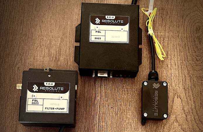
- Resolute Dynamics helps keep this under control with digital commissioning checklists, automated test data capture, one-click document bundles, integration with fleet platforms, and templates aligned with different national rules.
What Is a Post-Installation Speed Limiter Audit?

A post-installation speed limiter audit, also known as a speed limiter installation audit or speed governor compliance audit, is a formal sign-off carried out immediately after you fit, replace, or reprogram a speed limiter on a vehicle.
In the workshop it looks like this. The technician finishes the mechanical and electrical work, then shifts into “auditor” mode and systematically checks that:
- All hardware is solidly mounted, away from heat and moving parts, and wiring follows the intended route.
- The speed limiter communicates correctly with the engine ECU and any relevant CAN bus networks, without throwing errors.
- Calibration is set to the required governed speed and adjusted for the actual tire size, axle ratio, and local legal tolerance.
- Tamper seals are applied to all relevant access points, recorded with seal numbers, and photographed if policy requires.
- A road test, DTC scan, and full documentation set have been completed so the vehicle is ready for any regulatory or insurance-level scrutiny.
Why Post-Installation Audits Are Non-Negotiable
Bolting the box in and punching some numbers into the laptop does not mean the job is safe or compliant. A lot can go wrong between “installed” and “proven.” The post-installation audit is how you close that gap and prove to yourself, your driver, and a regulator that the limiter actually does what it is supposed to do.
Modern speed limiters live inside a pretty crowded electronic environment. They sit on CAN bus networks, talk to ECUs, and in many fleets they feed or read from GPS and telematics systems. A small mistake that looks harmless on the bench can bite you later. Things like:
- A weak or dirty ground that only drops voltage when the starter hits or lights are on full load.
- An incorrect speed source, such as tapping the wrong CAN ID or taking a wheel signal from the wrong axle.
- A firmware mismatch that makes the limiter react late, hunt around the set speed, or upset the cruise control strategy.
In the real world, those kinds of issues can:
- Stop the limiter from intervening at the correct speed, or let it overshoot when loaded downhill.
- Interact badly with cruise control, engine braking, ABS/ESP, or advanced driver assistance systems.
- Trigger DTCs, or worse, hide or mask the ones you actually need to see.
From a compliance angle, regulators are getting far more serious about proof. A fleet speed limiter acceptance test record for each vehicle is becoming standard. After a serious collision or during a detailed audit, you may be asked to produce things like:
- A fully completed and signed commissioning checklist for that unit.
- A clear calibration verification certificate that shows settings, method, and tolerance.
- Evidence of tamper seal application, with seal numbers and positions logged.
- A complete regulatory submission package that ties the vehicle, device, calibration, and tests together.
Without those records, you are relying on memory and trust. Even if your technicians did everything right, you may struggle to convince an investigator who is looking for hard paper or digital proof.
Complete Post-Installation Audit Checklist (15 Points)
A strong audit walks through 15 verification points. You cover the mechanical install, wiring, CAN bus communication, power and ground, speed signal source, calibration accuracy, ECU compatibility and DTC status, tamper sealing, GPS fix, HMI behavior, driver training, fleet records, documentation, and any formal regulatory submission.
A structured speed limiter verification checklist means every vehicle is commissioned the same way, no matter which workshop or technician touches it. Below is a field-tested 15-point framework, grouped into three logical blocks.
Physical & Electrical (Points 1–5)
This first block is about getting the basics right. If the hardware is wrong, nothing else will save you. These checks focus on the mechanical mounting and the electrical fundamentals that keep the limiter alive and stable.
- Physical mounting of the speed limiter unit
Start by looking at where and how the unit is mounted, not just that “it fits.” Confirm the device is:- Bolted to a solid, low-vibration surface such as a rigid bracket or structural panel, not cable-tied to a harness or a flimsy trim piece.
- Oriented exactly as the manufacturer specifies. Some units care about direction, access to cooling air, or keeping connectors pointing down to shed water.
- Protected from heat, spray, direct road grime, and any moving linkages or pedals. There should be no chance of contact under full suspension travel or cab tilt.
Then look at cable routing with a critical eye. Harnesses should be clipped or tied away from sharp edges, exhausts, steering shafts, and articulated joints. You want gentle bends, good strain relief, and enough slack to handle vibration without rubbing through insulation over time.
- Wiring integrity and connections
A proper wiring inspection is more than “everything’s plugged in.” You are looking for long-term reliability. Work through the harness and confirm:- There is no exposed copper, crushed insulation, badly crimped joints, or twisted-and-taped splices. Heatshrink, proper crimps, or OEM-approved connectors should be the standard.
- All connectors are fully seated until their locks click. Any unused leads are safely insulated and secured, not left to swing and chafe.
- Fuses and circuit protection match the device specification and are located where a technician can actually find and test them later.
Any deviation from the original wiring diagram, such as a changed feed point or added splice, needs to be written down. Document repairs done during the audit and why they were needed. That record helps when you troubleshoot an issue months later.
- Power supply verification
A lot of intermittent limiter complaints come back to lazy power checks. During the audit, confirm that:- The limiter sees the correct supply voltage for the vehicle platform, usually 12 V on light vehicles and 24 V on most heavy trucks and buses.
- Voltage at the limiter does not collapse during cranking, heavy accessory use, or when other high-draw devices kick in. Use a meter or data logger, not just a guess.
- The power feed is taken from the intended circuit. Some devices must be on an ignition-switched source, others need permanent live with an internal wake-up strategy. Follow the manual, not habit.
If voltage margins are tight, fix that now. Moving the feed or cleaning up corroded joints is a lot cheaper than chasing random limiter resets on the road.
- Ground connection quality
Poor grounds are one of the most common hidden faults I see. They work fine in the bay and then fail the first wet winter. As part of the audit, confirm that:- The limiter ground is bolted to clean, bare metal. Scrape away paint, rust, and underseal, then refit with a star washer or similar to bite in.
- The resistance between the limiter ground and the battery negative is within manufacturer limits. Do not guess. Put a meter on it.
- You are not stacking the limiter onto a “maybe” ground that already has several unknown devices hanging off it. Create or use a known good point.
If you have any doubt, create a new dedicated ground point or run a direct return. It costs minutes now and saves hours of fault-finding later.
- Speed signal source verification
The limiter is only as honest as its speed signal. If that input is wrong, your governed speed is wrong. During the audit, verify:- Exactly which source you are using. That might be a wheel speed sensor, gearbox output, vehicle speed from CAN, or a dedicated sensor supplied with the kit.
- The wiring or CAN mapping is correct for that source. Check pinouts, CAN ID tables, and any OEM-specific notes. Do not rely on “we always use that wire.”
- Signal plausibility by comparing indicated speed against GPS at a steady, moderate speed on the road. You are not aiming for perfect calibration here, just checking that the numbers make sense and are not wildly off.
This is also a good time to plan GPS sync verification during the road test, especially if your telematics platform or tachograph is part of your compliance evidence.
Communication & Calibration (Points 6–10)
Once the basics are solid, you move into the electronics. Here you are checking that the limiter behaves properly in the vehicle’s digital world, does not upset existing systems, and actually holds the speed you think it does.
- CAN bus integration verification
For CAN-connected limiters, guesswork is dangerous. During CAN bus integration verification:- Confirm that the limiter is plugged into the correct CAN network, such as CAN1 vs CAN2, or the chassis vs body network. Some vehicles run several separate buses.
- Use your scan tool or manufacturer software to verify that the expected CAN IDs are present and that the limiter is receiving and, if applicable, sending the messages specified in the installation manual.
- Check that no CAN errors, bus-off events, or abnormal traffic loads are being logged in any ECU while the limiter is powered and active.
On trucks with multiple ECUs, look for side effects. The limiter should only interact with the ECUs it is meant to, without disturbing ABS, stability control, body controllers, or telematics devices living on the same bus.
- ECU compatibility confirmation and DTC scan
A clean ECU compatibility check is a key part of the audit. Here is how you approach it:- Run a full DTC scan before installation and save the report. After installation, scan again and compare. You want to see what changed.
- Confirm that no new permanent or pending DTCs have appeared that can be linked to the limiter connection, such as speed signal faults, torque reduction conflicts, or CAN communication errors.
- Actively check cruise control, ABS/ESP, and any advanced safety systems where possible. They should behave normally with the limiter present and active.
If you see conflicts, stop and deal with them. Do not just clear codes and hope. Follow your internal ECU compatibility check guidance, and escalate tricky cases rather than sending an unpredictable truck back out on the road.
- Calibration accuracy test
The audit is where you verify calibration, not where you rush through it. Your calibration accuracy test should:- Check that the governed speed in the limiter settings matches your fleet policy and any national limit. For example, 90 km/h for a European heavy truck, 56 mph in some other markets.
- Confirm that tire size and axle ratio have been entered correctly where the device needs that data. A wrong rolling radius can easily move you 3–5 km/h out.
- Be validated via GPS at or close to the governed speed during the road test. Your goal is to check that real-world top speed sits inside legal tolerance.
If the limiter allows configuring tolerance, such as ±3 km/h, make sure you are inside the limit required by local law, not just “near enough.” For detailed calibration steps, keep technicians pointed to your defined process on calibration during audit.
- HMI (driver interface) verification
Drivers need clear and predictable feedback. During HMI verification:- Watch that any limiter-related warning lights or icons come on briefly at ignition as a self-test. A dead lamp can hide a serious fault.
- Check that the limiter-active indicator or text clearly shows when the system is holding the vehicle back, both with pedal and with cruise control.
- Listen and look for nuisance alarms or cryptic messages that drivers will complain about or ignore. Confusing HMI is one of the fastest ways to get drivers working around systems.
If the limiter is integrated into the OEM instrument cluster, navigate through the menus and confirm that the displayed governed speed and system status match what you actually set in the device.
- Tamper seal application and record
The tamper seal application stage is your front line against post-install tinkering. During the audit:- Seal any access point that could be used to change calibration or bypass the limiter. That might be device covers, inline harness connectors, programming ports where required, and any manual override switches.
- Record every seal number and its location on the commissioning checklist and on the calibration verification certificate. Be specific so someone else can verify it later.
- Take clear photos for the vehicle file on medium- or high-risk fleets, especially where multiple parties handle maintenance.
For more detailed sealing approaches and what different regulators expect, steer technicians to your tamper seal check documentation and training material.
Documentation & Compliance (Points 11–15)
The last block is what makes your work defensible. Hardware and calibration can be perfect, but if you cannot prove it, your position during an investigation is weak. These checks close the loop.
- Post-installation road test results
A post-installation road test is a non-negotiable piece of the audit. Confirm that:- The road test was carried out according to your acceptance test protocol, including warm-up, governed speed run, and threshold behavior checks.
- Results have been documented with GPS screenshots or downloaded logs linked to the specific vehicle and job ticket.
- The test has been signed off by the technician, and by a supervisor or quality controller where your policy calls for a second set of eyes.
If the test turned up odd behavior, that should be logged along with the corrective work and any re-test carried out.
- Driver training confirmation
A limiter the driver does not understand is a limiter that will get blamed for everything. During the audit, record that:- The driver, or at least the driver’s supervisor, has been briefed on how the limiter behaves, what the HMI indicates, and what “normal” feels like at the limit.
- They know what to do if they suspect a fault, such as sudden loss of power or unexpected warnings. The default should be: report immediately, do not try to bypass.
- Any written driver information, such as cab cards, leaflets, or app-based instructions, has been provided or updated.
For large fleets, this step is often linked to a short e-learning module or toolbox talk that drivers complete when new limiter settings roll out.
- Fleet management system record update
Your fleet management system record is where all the audit data should land. Update it so that it includes:- Vehicle details such as VIN, registration plate, and internal fleet unit number.
- Limiter device serial number, model, and firmware version that is currently installed.
- The governed speed setting, any tolerance used, and the date and time of commissioning.
- Technician ID, workshop location, and a pointer to where the full audit file is stored.
Many fleets build this into their regular inspection program and treat each audit as an audit as calibration verification milestone. That way, fleet-wide limiter settings can be reviewed and aligned over time.
- Documentation completeness check
Before anyone hangs the keys back on the board, run a quick but thorough documentation completeness check:- Is the commissioning checklist fully filled in, including any “N/A” fields where required, and signed where signatures are expected?
- Is the calibration verification certificate prepared, with correct units, method, results, and seal references?
- Are the road test log and DTC scan reports attached, named clearly, and linked to that specific vehicle?
- Is the tamper seal log completed with matching numbers and positions?
This is where digital workflows shine, because they simply will not let a job close until every mandatory document is in place.
- Regulatory submission package prepared
In regions where you must formally declare limiter installation or upload records, you need a tidy regulatory submission package. For those vehicles:- Compile the required forms and evidence into a single pack, either as a PDF or a structured electronic submission.
- Check that all fields match the country or state template, including IDs, units, and any required technical details like gross weight or axle count.
- Record the submission ID, acknowledgment email, or portal receipt number and store it with the vehicle’s record.
Having this ready from day one is far easier than trying to rebuild it when an inspector or insurer comes calling months later.
Post-Installation Road Test Protocol
A workshop-only audit is not enough. The limiter has to prove itself on the road, under real conditions. A consistent road test protocol removes guesswork and gives you comparable evidence across the fleet.
Your post-installation road test should be written down, repeatable, and realistic. In practice, that means driving at governed speed for at least a couple of minutes, cross-checking with GPS, probing behavior just below and right at the limit, confirming HMI operation, testing cruise control interaction, and running a full DTC scan after the drive.
Step-by-Step Road Test Procedure
- Pre-drive checks
- Confirm every physical and wiring item on the commissioning checklist is complete. The road is not where you find loose brackets or hanging harnesses.
- Hook up the scan tool and make sure there are no active critical DTCs that could affect the test or safety. Deal with any red flags before heading out.
- Verify that your GPS device, workshop tablet, or app is ready for the GPS cross-check. It should have a clear sky view and be logging speed and, ideally, route.
- Warm-up and base speed verification
- Drive to a safe test route, ideally a dual carriageway or highway where the legal limit is at or above your governed speed and traffic conditions allow a steady run.
- Hold a constant speed about 10 km/h below the governed speed for a minute or two. You are looking for smooth engine behavior and a stable speed signal, not hunting or odd surging.
- If you can see ECU parameters on your diagnostic tool, compare ECU-indicated speed with GPS at this base speed. They should be close enough to confirm the speed source is reasonable.
- Governed speed test (2+ minutes)
- Increase speed gradually until the limiter starts to intervene. This should be predictable and repeatable, not sudden or late.
- Maintain the vehicle at or near the governed speed for at least 2 minutes, traffic and road allowing. Avoid sharp gradients that may mask behavior.
- Record:
- The vehicle’s indicated speed on the dash compared to the GPS-measured speed.
- Any oscillation or “hunting” behavior where the truck repeatedly surges and drops a few km/h around the setpoint.
- Whether the true top speed stays within your allowed tolerance band for the whole period.
If you see large discrepancies or unstable behavior, that is a sign to revisit calibration or speed signal configuration before the truck goes back to work.
- Threshold behavior test (10 km/h below and above)
- At roughly 10 km/h below the limit, confirm there is no premature intervention. The vehicle should behave like a normal truck with full response to throttle.
- Where it is safe and legal, gently try to nudge the speed slightly past the governed value. The limiter should consistently prevent meaningful overshoot.
- Make notes on how power is reduced. A smooth reduction is typically preferred. Harsh cut-offs can unsettle drivers and, in some conditions, affect stability.
- HMI and warning verification
- Watch the limiter-active indicator or message when the system holds speed. It should engage and release cleanly and be obvious to a driver paying reasonable attention.
- Check for nuisance warnings that appear during normal driving but do not indicate real problems. Those tend to trigger unnecessary workshop visits or driver workarounds.
- Cruise control interaction test
- Set cruise control a few km/h below the limit and check for steady operation. The truck should hold speed without noticeable surging.
- Increase the cruise set speed carefully until it reaches the governed value and the limiter has to control things. Watch how the two systems interact.
- Confirm you do not get unsafe behavior such as rapid acceleration-deceleration cycles, random cruise canceling, or strange warning messages.
If there is any doubt here, adjust your configuration or consult your ECU compatibility check playbook before releasing the vehicle.
- Post-drive DTC scan
- Back in the workshop, run a fresh DTC scan post-install to see what the vehicle thought of that test drive.
- Pay close attention to CAN communication issues, engine torque control faults, and speed or wheel sensor errors that only appear under limiter operation.
- Attach this scan result to the vehicle’s commissioning record so anyone reviewing the job later sees a clean before-and-after trail.
- Road test sign-off
- Fill out a structured log with the date, weather, route, traffic conditions, and test results. Include notes on any anomalies and what you did about them.
- Have the technician sign to confirm the test was performed as per the acceptance test protocol, and get a supervisor sign-off where your process requires it.
Expert tip: Use the same GPS hardware or approved app across your fleet for governed speed validation. Consistent tools and methods are much easier to defend during external audits or legal reviews.
Documentation Package for Regulatory Submission

The technical work is only half the job. Without a clean paper or digital trail, you have very little to stand on if something goes wrong. That is where the regulatory submission package comes in.
Think of this package as a bundled story of what you did, who did it, how it was tested, and what the limiter was set to when the vehicle left the shop. You will build it from standard components such as the installation certificate, calibration certificate with seal numbers, road test report, DTC scan, technician credentials, and full device and vehicle identification.
Core Documents to Include
- Installation certificate
- Full vehicle identification, including VIN, registration, and any internal fleet ID used in your systems.
- Limiter device details such as make, model, serial number, and hardware revision so there is no confusion over which box is fitted.
- Installation date, workshop name, and the technician’s name or ID number responsible for the physical work.
- A short summary of the mounting location and key wiring connections, especially if you deviated from a standard layout.
- Calibration verification certificate
- The final governed speed setting with units, such as 90 km/h or 56 mph, clearly written and unambiguous.
- A reference to the calibration method used, for example “per OEM procedure,” “per national standard XYZ,” or “per fleet policy ABC.”
- Tolerance and test results, including GPS-verified readings, date and time of the test, and any required environmental conditions if a regulator specifies them.
- Associated tamper seal application details, including each seal number and where it was applied on the limiter or harness.
- Post-installation road test report
- Details of the route used, the speed segments tested, and how long the vehicle was held at governed speed.
- Observed differences between GPS and dash-indicated speed over the test, especially around the limit.
- Comments on limiter behavior such as smoothness, hunting, overshoot, and any driver feedback captured during or after the test.
- DTC scan report
- Pre-install and post-install DTC snapshots, preferably marked or color-coded so changes are easy to see.
- Notes confirming that existing unrelated faults were present before the limiter work and were not caused by it.
- Clear evidence that no safety-critical codes remain unresolved when the vehicle is returned to service.
- Technician certification and authorization
- A copy, ID, or internal reference for technician training specific to that limiter type and any relevant OEM systems.
- Any OEM or regulator-approved installer IDs that are required in your jurisdiction.
- The technician’s signature (or authenticated digital sign-off) confirming they followed the official procedure and checklist.
- Device and firmware details
- Device serial number, hardware revision, and current firmware or software version loaded on the limiter.
- Any configuration ID, checksum, or profile name provided by the manufacturer so you can prove which configuration was used.
- A reference or link to release notes if the firmware version includes safety or compliance-related fixes that influenced your choice.
Structuring the Regulatory Submission Package
Every country and even some states have their own format, but an internal standard layout makes everyone’s life easier. A typical in-house package might include:
- A cover sheet summarizing vehicle details, limiter model, governed speed, and key dates. This is the page inspectors usually scan first.
- Copies of the signed installation certificate and calibration verification certificate, grouped together so the narrative is clear.
- Appendices that hold:
- Road test logs and GPS comparison data, ideally with timestamps and clear labels.
- DTC scan reports showing pre- and post-install status.
- Photographs of the installation and tamper seals, printed or embedded for quick visual verification.
- An optional QR code or web link pointing to the vehicle’s electronic record in your fleet platform, so regulators or internal auditors can pull further history if allowed.
Once compiled, you can use the same package for official regulatory submissions, insurer questions, internal safety audits, and as a reference when that vehicle comes back for recalibration, firmware updates, or limiter replacement.
How Resolute Dynamics Streamlines Post-Installation Audits
Paper systems work until they do not. Lost sheets, half-completed forms, and illegible notes are exactly what hurt fleets in investigations. That is why many operators move to a structured digital approach like the Resolute Dynamics commissioning process.
The goal is simple: guide technicians through the same thorough audit every time, capture hard data directly from tools, and produce a clean, regulator-ready record set without hours of admin.
Digital Commissioning Checklist on Technician Tablet
Instead of chasing clipboards and rebuilding missing records, technicians follow a guided commissioning checklist on a tablet or workshop PC:
- Mandatory fields, drop-downs, and photo prompts prevent key data from being skipped. The job cannot be signed off with half the boxes blank.
- Contextual help explains tasks such as CAN bus integration verification or ECU compatibility confirmation in plain, on-screen language so even newer techs know what to look for.
- Each step is timestamped and tied to a user ID, creating a strong audit trail that shows who did what and when, which auditors and insurers appreciate.
Automated Test Result Capture
Manual copying of test results into forms is where errors creep in. During the post-installation road test and diagnostic work, a Resolute-style setup can pull in data automatically from compatible tools:
- GPS speed traces and route logs come straight from the tablet or telematics device and are stamped with vehicle and job identifiers.
- DTC scan results upload from diagnostic tools into the job record so nobody is retyping error codes or losing printouts.
- Limiter configuration readouts, including governed speed and firmware version, are imported directly from the unit, which removes transcription errors and “fat finger” problems.
One-Click Documentation Package Generation
Once the technician has completed the checklist, the system can assemble all the outputs for you in a couple of clicks:
- An installation certificate and calibration verification certificate populated with job data and embedded seal numbers, ready to sign digitally or on paper if needed.
- Road test and DTC scan summaries formatted the way regulators and insurers like to see them, with clear headers and traceability.
- A compiled regulatory submission package PDF that can be uploaded to official portals or saved to your compliance folders without manual cutting and pasting.
Fleet Management System Auto-Update
Keeping the fleet system in sync is where many operations fall down. With Resolute Dynamics tied into your platform:
- The governed speed, installation date, limiter model, and serial number automatically update the fleet management system record once the audit is complete.
- The system can schedule the next review or recalibration date based on your maintenance rules, feeding straight into your audit as calibration verification cycle and work planning.
Regulatory Templates Per Country
Different markets ask for different fields. Trying to remember all that in your head is asking for trouble. With regulatory submission templates per country baked into the system:
- Forms and screens show only the required fields for that jurisdiction, such as operator license numbers, axle counts, or emission class, reducing mistakes.
- Generated forms align visually with official layouts where the regulator allows, so they look familiar to inspectors.
- Policy or legal changes can be updated once in the system and pushed to all workshops, rather than relying on everyone updating their own spreadsheets and paper forms.
For fleets working across borders, this kind of standardization keeps documentation consistent even as rules evolve. That means fewer surprises at roadside checks and less rework when auditors show up.
Common Mistakes in Post-Installation Speed Limiter Audits (and How to Fix Them)

- Skipping the road test due to time pressure
Risk: Problems like overshoot, hunting around the limit, or weird ECU interaction often only show up on the road. If you skip the road test, you discover them when a driver complains or an inspector does.
Fix: Build the post-installation road test directly into your acceptance test protocol and scheduling. Treat it as mandatory, with a booked time slot, not as an optional extra if there is time. - Treating calibration as “set and forget”
Risk: Changes in tire size, axle ratio, or even firmware can shift real-world speed away from what is written in the certificate, pushing your trucks above legal limits.
Fix: Always run a calibration accuracy test against GPS and compare it with the limiter and ECU readings. If adjustments are needed, follow your documented calibration during audit process and issue updated certificates. - Weak documentation and missing signatures
Risk: During an investigation, missing signatures or half-completed forms look almost as bad as no audit at all, even if the install is technically sound.
Fix: Move to standardized forms or digital workflows that physically prevent a job from closing until all required fields, scans, and signatures are captured. - Inadequate tamper sealing and poor seal logs
Risk: If a limiter is easy to bypass and you cannot prove when or by whom seals were broken, liability gets very messy very quickly.
Fix: Define a consistent tamper seal application pattern per vehicle type, and keep a tight seal number log linked to each calibration certificate. Point technicians to your tamper seal check guidance so they all follow the same standard. - No ECU compatibility check after install
Risk: Hidden DTCs, torque limitation conflicts, or strange behavior in cruise control and stability systems go unnoticed until a serious event puts them under a microscope.
Fix: Make an ECU compatibility check and a proper DTC scan post-install part of every audit. Compare pre- and post-install reports rather than just clearing codes. - Failure to update fleet records
Risk: You end up with a mixed fleet where nobody really knows which trucks are limited to what, which complicates compliance checks and confuses drivers.
Fix: Tie every completed audit to a fleet management system record update, including governed speed, limiter model, serial, and calibration date. That data should be visible to managers and planners. - Not planning for re-audit after repairs or replacements
Risk: Replacement limiters, ECUs, speed sensors, or gearbox swaps go in, the truck leaves, and nobody ever re-verifies governed speed or tamper sealing.
Fix: Treat any significant change that can affect speed control as requiring a new speed limiter commissioning audit. Use your process for an audit after replacement so nothing slips through.
Use with: Calibration & reset procedure – Seal-inspection procedure – RPM regulator troubleshooting.
FAQ: Post-Installation Speed Limiter Audits
Below are straight answers to the questions fleet operators and workshop managers ask most about speed limiter auditing.
How long does a post-installation speed limiter audit take per vehicle?
On a typical heavy vehicle, once your team is used to the process, a full audit with physical checks, CAN bus integration verification, a proper road test, and documentation usually takes around 60–90 minutes. The first few installs with a new limiter model or on a new vehicle platform may take longer while you refine the playbook.
Who should perform a speed limiter installation audit?
The audit should be carried out by a trained, authorized technician who knows that limiter family, has a working understanding of the vehicle’s ECU setup, and is aware of local regulations. Ideally, the installer completes the technical work, then a second qualified person reviews the commissioning checklist and signs off critical items, especially for high-risk or regulated fleets.
Is a post-installation audit legally required?
In many regions, the law requires evidence that speed limiters are installed and calibrated correctly, even if the regulation does not explicitly use the phrase “post-installation audit.” Running a structured speed governor compliance audit and keeping the records gives you that evidence and makes life easier during roadside inspections, operator audits, or after an incident.
How much does a speed limiter commissioning audit cost?
Costs depend on workshop labor rates, how complex the vehicle is, and how your process is set up. Some installers bundle the speed limiter commissioning audit into a fixed installation price. Others bill it as separate time for diagnostics, road testing, and documentation. For fleets looking at risk, the real cost is in skipping the audit and then facing legal or insurance challenges later.
What happens if the audit identifies an issue?
If the audit turns up wiring errors, calibration problems, DTCs linked to the limiter, missing or broken seals, or odd behavior on the road, the vehicle should stay out of service until it is fixed. The technician corrects the fault, repeats the relevant parts of the audit, often including another post-installation road test, and updates the documentation to reflect the rework and final results.
Do I need to re-audit after firmware updates or component changes?
Yes. Any change that can affect speed control should trigger at least a partial re-audit. That includes limiter firmware updates, limiter replacements, speed sensor work, ECU swaps, or gearbox and axle ratio changes. Many fleets build this into their audit as compliance answer strategy so they can show regulators and insurers a clear history of how each vehicle has been managed.
How is a post-installation audit different from ongoing monitoring?
The post-installation audit is a point-in-time acceptance test carried out right after install or major work, with a clear pass/fail outcome. Ongoing monitoring relies on telematics, tachograph data, or smart alerts to spot anomalies in limiter performance over weeks and months. Both matter, but they serve different purposes and should be documented in different parts of your fleet policy.
Can GPS alone be used to prove governed speed compliance?
GPS is an excellent independent reference for checking real-world speed, and regulators increasingly trust it. But in most cases, they still expect to see that limiter settings and ECU data support what your GPS logs show. Your calibration verification certificate is strongest when it combines limiter configuration, ECU readings, GPS comparisons, and clear test logs.
Final Summary and Next Steps
A well-run post-installation speed limiter audit is far more than a quick spin and a sticker. It is a structured process that proves the limiter is installed safely, calibrated accurately, sealed properly, and supported by documentation that will stand up under scrutiny.
By adopting a 15-point speed limiter verification checklist, a standardised post-installation road test, and a consistent regulatory submission package, fleets cut down on technical faults, reduce legal exposure, and give drivers predictable, transparent limiter behavior. Treat the audit as a formal acceptance test and a safety gate, not a box-ticking exercise.
If you are ready to tighten up your process or scale it across more sites, the Resolute Dynamics commissioning process can help you automate checklists, pull test data directly from tools, generate clean documentation, and keep fleet records aligned with changing regulations.
Next step: Lay your current process next to the 15-point checklist above. Mark where you already have strong controls, highlight the gaps, and decide when re-audits are triggered, especially after replacements, recalibrations, firmware changes, or major driveline work.

The Resolute Dynamics team designs and manufactures speed limiters (SLD), GPS tracking, and automotive safety systems used on 200,000+ vehicles across 20+ countries. We write about fleet compliance, road-safety regulation, and vehicle-safety technology, including Malaysia’s JPJ SLD mandate, UAE RTA rules, and global standards like UN R89, to help fleet operators and transport businesses stay safe and compliant.