TL;DR: On a manual transmission, an RPM regulator is only as good as the signals and calibration you feed it. Gear choice, clutch use, and driver style all change engine speed faster than an automatic ECU is used to seeing.
Most “inconsistent” RPM limiter behavior comes from bad or missing inputs, or from automatic-style settings copied onto a manual, not from a failed governor. Verify signals, tune per-gear limits, add proper clutch blanking and hysteresis, and most problems disappear.
Key Takeaways
- Manual transmission RPM regulation is more involved than on an automatic because a single engine RPM can mean crawling in 2nd or cruising in 6th, depending on the gear.
- False triggers often show up during downshifts, clutch engagement spikes, and near-threshold RPM “hunting,” especially if thresholds, hysteresis, and limits are not tuned per gear.
- Critical inputs include the crankshaft position sensor, tachometer signal source, gear detection module, clutch position sensor, and any J1939 engine speed PID data on the CAN bus.
- Most “RPM limiter problems” trace back to calibration issues: wrong gear-dependent RPM thresholds, missing or tiny clutch blanking windows, or poor neutral/idle bypass logic.
- Good diagnostics compare logged RPM, gear, clutch and governor events against actual driver behavior and shift patterns, not just what the driver reports from memory.
- Features like per-gear RPM limit tables, clutch engagement blanking, downshift hysteresis, neutral detection, and sensible governor intervention delay are essential for manual transmission fleet vehicles.
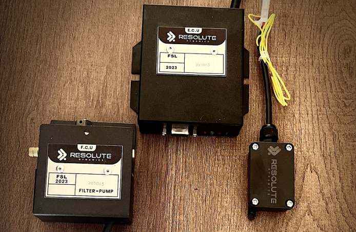
- Resolute Dynamics RPM governance systems and similar platforms rely on multiple sensors to separate genuine over-speed from normal shifting and engine braking behavior.
- If a device proves truly unrepairable after proper testing, use a structured replacement if unrepairable plan instead of endless “try this” recalibrations.
Quick Definition: What Is an RPM Regulator in a Manual Vehicle?
What is an RPM regulator? An RPM regulator (also called an RPM governor or engine speed limiter) is an electronic control that watches engine speed through a tachometer signal or crankshaft position sensor and steps in with fuel cut, throttle limit, or torque reduction when RPM climbs above a programmed threshold.
In manual transmission fleet vehicles, modern systems usually tie into several points:
- Crankshaft position sensor RPM signal or tachometer signal so the unit always knows true engine speed instead of guessing.
- Transmission gear detection or CAN-based gear state so limits can change by gear.
- Clutch position sensor and neutral detection to understand when the driveline is connected or free.
- J1939 engine speed PID on vehicles with a CAN bus, giving clean digital RPM data that matches ECU readings.
Advanced platforms such as Resolute Dynamics RPM governance blend all of these inputs. They run different RPM limits in each gear, ignore known “noise” caused by clutch use, and avoid stepping on normal shifting or engine braking behavior.
Why RPM Regulation Is More Complex in Manual Vehicles
Automatics keep the relationship between RPM and road speed fairly tight. The transmission decides the gear, and the ECU already knows exactly what it did. With a manual, the driver is in charge of gear choice, clutch timing, and throttle. The same 3,000 RPM can mean “about to launch” in 2nd or “steady cruise” in 6th.
Any RPM regulator manual transmission setup that ignores that difference will cut power right when the driver needs it, or will constantly get fooled by normal shifts and engine braking.
The Gear Ratio–RPM Relationship in Manual Gearboxes
Every gear in a manual transmission has its own ratio between engine speed and road speed. That ratio is what ties RPM to how fast the vehicle moves.
As a rough example, 3,000 RPM in 2nd gear might give you around 25 mph. The same 3,000 RPM in 6th might be closer to 65 mph, depending on axle ratio and tire size. So in practice:
- Same RPM ≠ same road speed once you start changing gears.
- Engine RPM can swing very quickly during shifts, even when the truck’s road speed barely changes.
- Engine braking RPM during a well-timed downshift can be high while actual vehicle speed is stable or even dropping.
Any RPM regulator manual transmission package has to respect this gear ratio–RPM relationship. If it just watches RPM blindly, it will treat a high engine braking RPM in 3rd on a hill as “overspeed” even though the driver is under full control and scrubbing speed.
Driver Behavior in Manual Gearbox Operation
On a manual, the driver is a big part of the control loop. They decide:
- Exactly when to upshift and downshift.
- How fast to lift off the throttle and how quickly to release the clutch.
- Whether to lean on engine braking RPM on a descent or ride the service brakes instead.
- How deep to push the accelerator while in gear or while transitioning through a shift.
That hands-on control creates fast, short-lived RPM changes that confuse simple governors. You’ll often see:
- A clutch engagement RPM spike when the driver lets the clutch out aggressively, especially under load.
- A downshift RPM overshoot when the driver catches a lower gear at a higher road speed, letting the engine spin up to match.
- RPM vs road speed manual inconsistencies in data logs if the system is guessing the wrong gear or missing clutch transitions.
An RPM governor that behaves nicely on automatics can feel “jerky” or “random” on manuals if it ignores real driver behavior. In practice, that’s where most complaints start.
Why Gear and Clutch Detection Are Essential
To separate a real over-rev from a normal gear change, a serious RPM governor for a manual transmission fleet vehicle has to know two things: what gear it’s in, and what the clutch is doing.
Good systems rely on:
- A gear detection module or CAN-based gear information from the ECU or TCU so the governor isn’t guessing.
- A clutch position sensor so it can tell the difference between a loaded engine and one free-spinning during a shift.
- Reliable neutral detection so the regulator backs off when the vehicle is idling or coasting out of gear.
Without those pieces, a speed governor manual gearbox configuration gets blamed for “random cuts” and “flat spots.” What’s really happening is the governor is working off half the story, then reacting to spikes and dips it doesn’t understand.
Common RPM Regulator Inconsistencies in Manual Vehicles
Out in the field, RPM regulator issues on manuals tend to fall into a handful of patterns. Once you recognize those, it’s much easier to tell if you’re chasing a broken part or just a calibration that doesn’t match how the truck is being driven.
The usual complaints sound like this:
- RPM limiter kicks in on normal downshifts.
- Engine “surges” or “hunts” right at the limit on the highway.
- Limiter flashes in on quick clutch work or throttle blips.
- Idle feels unstable, or the limiter is active even in neutral.
Downshift False Trigger
Scenario: Driver drops from 5th to 4th to pass or to hold speed on a hill. As the clutch comes up, RPM shoots up to match the lower gear. The RPM regulator sees that spike like it’s a runaway event and cuts fuel or throttle. The truck lurches, the driver loses the pass window, and you get a complaint.
Why it happens:
- The governor RPM threshold per gear is sitting right on top of the normal downshift RPM peak for that engine and axle combo.
- There is little or no downshift hysteresis, so even a tiny, clean overshoot trips the limiter instantly.
- The system has no meaningful clutch engagement blanking window, so it doesn’t ignore those short, expected spikes while the clutch is re-engaging.
Risk: Over time, drivers stop trusting the truck. Some will stop using engine braking altogether and lean on the brakes, which adds heat, wear, and risk on long grades. Others will rev the engine less when overtaking, stretching passes and making them more dangerous.
RPM Hunting (Oscillation Near Threshold)
Scenario: In top gear at highway speed, the driver holds the pedal where the engine makes good power. The RPM regulator trims power right as RPM hits the limit. RPM drops slightly, governor turns loose again, RPM climbs back, and this cycle keeps repeating. In the cab it feels like a constant gentle surge.
Technical description: That pattern is RPM hunting oscillation. The system is snapping on and off around the set limit instead of settling into a smooth top value.
Attributes of RPM hunting oscillation
- Cause: Limit set too close to the normal operating band with little or no hysteresis to separate “on” and “off.”
- Oscillation frequency: Often around 0.5–2 Hz, so you feel one or two surges every second.
- Governor response time: Typical reaction time is 50–300 ms from threshold crossing to intervention. Too-fast response exaggerates hunting.
- Fix method: Open up the hysteresis adjustment so the limiter releases at a lower RPM than it activates, and in some cases slow the control loop slightly.
- Typical hysteresis range: Around 50–200 RPM below the limit, adjusted based on engine inertia and driveline setup.
With proper hysteresis and a reasonable delay, the governor responds only to sustained overspeed, not every tiny ripple in RPM.
Clutch Spike False Alarm
Scenario: A confident driver rows through the gears quickly, maybe with a throttle blip to match revs. The tach needle flicks over the programmed limit for a split moment. The RPM limiter treats that like a real over-rev and jumps in, chopping power during an otherwise clean shift.
Cause:
- A large clutch engagement RPM spike caused by quick clutch work and sharp throttle changes.
- No or badly tuned clutch engagement blanking window, so the system “sees” everything during that transition.
- Governor logic using raw instantaneous RPM instead of a filtered or time-averaged RPM value that ignores short-lived spikes.
Clutch engagement blanking window attributes:
- Duration (ms): In practice, most setups land between 150–500 ms of masking after a clutch switch edge.
- Trigger: Rising or falling edge from the clutch position sensor, depending on how the system is wired.
- RPM spike ignored during window: Yes, usually within a configurable upper bound, so a brief, realistic spike isn’t treated as a hard over-rev.
- Configurable: Advanced governors like Resolute Dynamics RPM governance let you tune this window and spike allowance in software.
- Default setting: Often in the 250 ms range. That gets you in the ballpark, but fleets almost always need to adjust it to match their drivers and routes.
Without that blanking logic, you end up punishing skilled drivers for driving properly, and the limiter gets blamed for “killing the truck” during shifts.
Neutral Idle Conflict
Scenario: Truck is in neutral. Driver gives the engine a short rev to check response or the technician runs it up during a shop test. The RPM governor steps in even though the transmission is out of gear, or the idle controller and limiter start fighting, causing a wandering idle.
Why this happens
- No reliable neutral detection, or the signal is wired but not trusted by the calibration.
- One global RPM limit used regardless of gear or neutral, so neutral revs hit the same ceiling as loaded pulls in top gear.
- Idle control logic built into the ECU colliding with an external RPM limiter that isn’t aware of what the ECU is trying to do.
Neutral detection attributes:
- Detection method: Ideally a dedicated gear position sensor or a CAN-based neutral/gear state. In a pinch, some systems infer neutral from RPM vs speed behavior.
- Neutral RPM bypass: This can be off, partially active, or fully active. The best approach lets you set a separate neutral RPM ceiling for maintenance and checks.
- False neutral risk: Noisy sensors, CAN dropouts, or poor calibration in the gear detection module can briefly “fake” neutral and remove limits at the wrong time.
- Fleet configuration: You can run one neutral strategy across the fleet or tailor it per vehicle group, especially in mixed-use fleets.
- Driver notification: A simple dash light or indicator when a neutral bypass is active helps techs and drivers understand why the engine behaves differently.
A smart neutral setup lets you rev enough for diagnostics and warm-ups while still stopping someone from free-revving an engine into self-destruction.
Diagnostic Steps for RPM Regulator Issues
Most RPM limiter manual vehicle headaches can be sorted with a calm, structured diagnostic process instead of throwing parts at the truck. Start with a clear diagnostic flowchart. You can sketch your own or lean on our published diagnostic flowchart. That guide focuses on engagement issues, but the style of thinking carries straight over to RPM behavior.
Below is a practical, step-by-step process tailored to RPM regulator manual transmission inconsistencies.
1. Verify the RPM Signal Source
Your first job is simple: figure out where the governor is getting its tachometer signal. If that source is wrong or noisy, every other step is built on sand.
- Direct engine signal: Typically from the crankshaft position sensor RPM signal, which is a pulse-based reading from a tone wheel.
- Cluster tach signal: An analog or digital signal feeding the dash tachometer, sometimes tapped by aftermarket governors.
- CAN bus / J1939: Digital engine RPM from the J1939 engine speed PID, commonly PGN 61444, SPN 190.
Crankshaft position sensor RPM signal attributes:
- Signal type: Pulse signal, often from a VR (variable reluctance) or Hall-effect sensor.
- Pulses per revolution: Common count is in the 36–60 pulses/rev range, depending on the tone wheel pattern.
- Accuracy: Usually very tight, within a few RPM under steady conditions.
- Failure mode: You might see total signal loss, intermittent gaps, or noisy, jittery pulses.
- Diagnostic check: Use an oscilloscope to inspect the waveform. Look for clean, evenly spaced pulses that scale smoothly with RPM.
Checks:
- Compare ECU-reported RPM and governor-logged RPM at idle, at a slow raise through the revs, and at a steady cruise.
- Watch for sudden steps, odd spikes, or plateaus that don’t match what your ears or a handheld tach say.
- If using CAN/J1939, consider whether ECU signal interference or heavy bus traffic could be delaying or corrupting the RPM data.
2. Confirm Gear Detection Input
Once the RPM signal checks out, confirm how the RPM regulator knows which gear the truck is in. This is where many manual setups struggle.
- A dedicated gear detection module wired to transmission sensors or switches.
- Gear information broadcast by the ECU over CAN, if supported by the OEM.
- Software that infers gear from RPM vs road speed manual correlation, basically dividing one by the other and matching to known ratios.
Steps:
- Connect your diagnostic tool or governor software and display live gear state.
- Have the driver roll through gears 1–6 at low speed while you watch reported gear changes in real time.
- Note any missed shifts, obviously wrong gear values, delayed changes, or long periods reported as “unknown” or “neutral.”
If gear detection is sloppy, any gear-dependent RPM threshold logic will fire at the wrong time. That’s a straight path to “inconsistent” limiter behavior and driver frustration.
3. Review Per-Gear RPM Limit Configuration
Most modern governors, including Resolute Dynamics RPM governance setups, support a per-gear RPM table. On a manual, this is non-negotiable. One global value for all gears is asking for trouble.
Gear-dependent RPM threshold attributes (example)
| Gear | Typical RPM Limit | Note |
|---|---|---|
| 1st | 3,500–4,000 RPM | Lower to keep launches controlled and protect driveline parts. |
| 2nd | 3,800–4,200 RPM | Enough headroom for acceleration while still limiting wheelspin risk. |
| 3rd | 4,000–4,500 RPM | Good mid-gear band where many trucks spend time pulling. |
| 4th/5th (and higher) | 4,000–4,800 RPM | Higher to allow safe overtaking and merging in the engine’s power band. |
Configuration method: Limits are usually entered into a per-gear table within the governor software as part of a formal calibration procedure. On some systems you can log and tweak these tables over a remote connection.
Checks:
- Make sure top-gear limits aren’t so conservative that a loaded truck can’t accelerate safely up a grade or complete an overtake.
- Verify that low-gear limits don’t let a driver sit at redline in 1st or 2nd, which beats up clutches, gearsets, and sometimes axles.
- Check every limit against the engine’s actual redline and OEM recommendations. Leave some margin, but not so much that half the power band is locked out.
4. Analyze Clutch Position Sensor Input
The clutch position sensor is the governor’s eyes on what the driver is doing with the driveline. Without it, the system can’t tell a loaded pull from a free-rev during a shift.
Checks:
- Confirm wiring and polarity so that “clutch in” and “clutch out” states are reported correctly in the software.
- Log clutch status alongside RPM during test drives and verify that the clutch engagement blanking window is actually activating on each shift.
- If normal shifts still trigger the limiter, extend the blanking window or fine-tune whatever “max spike” parameter the platform offers.
If the clutch signal is dead, reversed, or stuck, the governor might assume the clutch is always pressed or never pressed. That leads to weird timing on fuel cuts and a limiter that feels unpredictable from the driver’s seat.
5. Compare Logged RPM Events Against Driver Shift Patterns
Once you trust the hardware inputs, tie everything back to what drivers are really doing. Data by itself doesn’t tell the full story unless you line it up with how the truck was being driven at the time.
- Pull logs for RPM, gear, clutch state, road speed, and governor interventions over a typical day or at least a dedicated test drive.
- Overlay that against driver shift timing, either from dashcam video, telemetry timestamps, or at minimum a detailed driver description right after a test run.
- Look for repeatable patterns. Does the limiter always trigger at the same RPM and same gear, or only with certain drivers or certain loads?
That comparison will usually point you toward one of three buckets:
- Mis-calibration: Limits too low, hysteresis too tight, or wrong assumptions about shift style.
- Sensor issues: Gear dropping out, clutch flag stuck, or RPM noise right before events.
- Driver misuse: Habits like flat-foot shifting, chronic over-revving, or riding the clutch that push the system past its reasonable envelope.
Always document what you find before making changes. Then you can tell if the next calibration pass actually improved things or just moved the complaints around.
Calibration Adjustments for Manual Vehicle RPM Governors
Once you know the wiring and data are clean, you can fix most manual transmission speed limiter issues on the laptop, not with a parts cart. In my experience, most of the time you’re fighting settings that were copied from an automatic or from a different duty cycle.
Per-Gear RPM Threshold Configuration
The core of any good manual setup is a solid per-gear RPM threshold table. You’re balancing drivability against mechanical sympathy, gear by gear.
Guidelines:
- Start with the engine manufacturer’s redline and torque curve. There’s no sense in limiting power below the useful power band unless policy demands it.
- Give higher gears slightly more headroom so drivers can use the engine’s power when merging, towing up grades, or overtaking.
- Pull limits down in lower gears to tame aggressive launches and protect the clutch, transmission, and driveshaft.
- Factor in actual load. A heavy vocational truck and a light van can’t always share the same table.
For platform-specific steps, check your system manual or review the generic calibration procedure and adapt it to your hardware. The main thing is to treat manuals as their own category, not a copy of auto settings.
Clutch-Engagement Blanking Window Tuning
The clutch engagement blanking window is your safety net against false triggers during normal shifting. Tune it wrong and the limiter will cut into every fast gear change. Tune it right and those shifts disappear in the logs.
Key parameters:
- Window duration (ms): As a starting point, 200–300 ms works on most drivers. Faster or more aggressive shifting might need closer to 350–400 ms.
- Activation trigger: Usually an edge on the clutch position sensor, either when the pedal is pressed or when it’s released, depending on design.
- Maximum ignored RPM: Some systems let you allow a certain RPM above the set limit during the blanking window, beyond which it will still intervene.
Practical approach:
- Have a competent driver make several “normal but brisk” shifts through all gears while logging clutch state and RPM.
- Measure how long RPM is unstable between clutch press and RPM settling in the new gear.
- Set your blanking window a bit longer than that typical duration without stretching it so far that true over-rev events slide through unnoticed.
Downshift Hysteresis and Governor Response
Hysteresis is the gap between the RPM where the limiter turns on and the RPM where it turns back off. Get this wrong and you see that annoying RPM hunting oscillation. Get it right and the limiter steps in smoothly and then stays out of the way.
Hysteresis attributes (for RPM hunting oscillation fix)
- Cause of oscillation: An activation point that sits right on top of the engine’s normal cruise RPM with almost no difference between “on” and “off.”
- Governor response time (ms): If the reaction is instant, even tiny noise or driveline lash can trip the limiter.
- Hysteresis range (RPM): As a starting point, 75–150 RPM is usually enough to calm down hunting, then you fine-tune from there.
Optimal tuning tips:
- Use a bit more hysteresis in high gears where you want a stable highway cruise without surging.
- Use slightly tighter hysteresis in the bottom gears where precise control of launch RPM matters more than ultrafine smoothness.
- Add a small governor intervention delay manual of around 100–200 ms so the system ignores quick spikes that vanish on their own.
Neutral Detection and Bypass Configuration
Neutral logic is where a lot of RPM vs road speed manual setups go sideways. The aim is simple: treat neutral differently enough that techs can do their work, while still stopping someone from abusing the throttle.
Neutral detection and bypass configuration
- Detection method: Ideally a gear position sensor or ECU neutral flag pulled over CAN. Fallback methods try to spot a pattern of RPM rising with zero road speed and no gear reported.
- Neutral RPM bypass: You can open the limit up in neutral or set a separate neutral-specific cap that’s higher than in-gear limits but still sane.
- False neutral risk conditions: Vibration shaking connectors, sensor drift, or buggy software can all fake neutral and leave the engine unprotected while actually in gear.
- Driver notification: A “limiter bypass active” or similar dash indicator makes it obvious when standard RPM control is not in full effect.
The sweet spot is a modest neutral cap. High enough for diagnosis, warm-up, or regen routines, but low enough to protect the engine if someone free-revs it in the yard.
Comparison: Common RPM Issues vs Calibration Fixes
The table below lines up common symptoms with the kinds of root causes and calibration changes that usually fix them in real fleets.
| Symptom | Likely Root Cause | Primary Calibration Fix |
|---|---|---|
| Limiter cuts power during downshift | No clutch blanking / low per-gear threshold | Enable or extend clutch blanking window and raise RPM limits slightly for gears commonly used in downshifts. |
| Surging near top speed in top gear | RPM hunting oscillation | Increase hysteresis range and add a small intervention delay to avoid rapid on-off cycling. |
| Limiter activates on quick clutch “blip” | Short/no blanking window; sensitive instant RPM trigger | Lengthen the blanking window and, where available, reduce sensitivity to transient RPM spikes. |
| Unstable idle or limiting in neutral | Poor neutral detection / no bypass | Verify neutral signal, then configure a neutral-specific RPM cap or bypass strategy. |
| Limit feels too “early” in low gears | Global RPM limit shared across all gears | Implement a per-gear RPM threshold table that relaxes higher gears and tightens lower ones. |
Common Mistakes When Troubleshooting Manual RPM Regulators (and Fixes)
Mistake 1: Assuming a Hardware Fault Before Checking Calibration
Problem: Swapping out the RPM governor, sensors, or even ECUs without first pulling the config. That racks up costs and downtime while the underlying mis-calibration stays put.
Fix: Always export and review the configuration before ordering hardware. Most RPM inconsistency speed governor complaints come from mismatch between thresholds, blanking logic, and actual real-world manual driving behavior.
Mistake 2: Ignoring Gear Detection Quality
Problem: Treating gear information as a “nice to have” and relying on RPM and road speed only. That leads to bad assumptions about driver intent and gear choice.
Fix: Validate the gear detection module or CAN-based gear signals under real driving conditions. If you can’t get clean gear data, select an RPM governor platform that has strong inferred gear algorithms designed for manual transmissions.
Mistake 3: Copying Automatic-Transmission Settings to Manuals
Problem: Reusing automatic calibration profiles on manuals. Tight thresholds, minimal clutch blanking, and basic neutral logic that work fine on autos usually cause jerky cuts and complaints on stick-shift trucks.
Fix: Maintain separate calibration profiles for manual and automatic vehicles. Make sure manuals have dedicated hysteresis settings, clutch blanking windows, and neutral handling tuned to manual driving patterns. For policy-level advice, check the manual vehicle RPM FAQ.
Mistake 4: Over-Restrictive Limits That Hinder Safe Overtaking
Problem: Setting high-gear RPM or speed limits so low that drivers can’t get into the usable power band when merging, passing, or climbing hills with a load.
Fix: Raise top-gear RPM thresholds to a level that still respects engine limits but allows short bursts into the power band. Document this rationale in fleet policy so safety officers and technicians are aligned.
Mistake 5: Not Considering ECU Interactions
Problem: Overlooking the stack of controls already on the vehicle. Cruise control, traction control, built-in ECU RPM or speed limits, and the external RPM regulator can all overlap and cause confusing symptoms.
Fix: Map all systems that can touch engine speed or torque. Then read up on ECU signal interference and coordinate settings, so multiple modules aren’t fighting for control.
See also: Calibrate & reset guide – Audit checklist – Seal-inspection procedure.
FAQ: RPM Regulator Issues in Manual Transmission Fleet Vehicles
Below are answers to questions technicians and fleet managers often raise after installing or adjusting manual gearbox RPM governors.
Why does the RPM limiter cut in when drivers try to overtake?
Most of the time, top-gear RPM thresholds are simply set too low, or the system isn’t distinguishing RPM vs road speed manual behavior by gear. The governor sees “high RPM” with no context and clamps down even though the pass is safe. Raise the top-gear limit within manufacturer guidelines, add moderate hysteresis, and keep low-gear limits a bit tighter.
Can I use the same RPM regulator settings for manual and automatic vehicles in my fleet?
That’s not a good idea. Driver behavior manual gearbox patterns are very different from automatics, especially under load and during downshifts. Manuals need proper per-gear RPM thresholds, clutch blanking, and strong neutral detection. Keep separate profiles and run a dedicated calibration procedure for each transmission type.
How much does a gear detection module typically cost, and is it worth it?
Pricing depends on vehicle and platform, but in practice the cost is easy to justify. Accurate gear detection dramatically reduces nuisance limiter events, driver complaints, and downtime chasing “ghost” faults. On systems like Resolute Dynamics RPM governance, solid gear detection is a core part of getting stable behavior on manuals.
Do RPM governors work with all types of manual transmissions?
Most modern RPM governors can work with a wide variety of manual transmissions as long as they see a clean RPM signal and have some form of gear or neutral detection. Very old or purely mechanical gearboxes might need additional switches or a dedicated speed governor manual gearbox kit to provide those signals.
What is the difference between an RPM governor and a speed governor on a manual vehicle?
An RPM governor watches and limits engine speed, while a speed governor focuses on road speed. On manuals, those two values don’t track each other perfectly because the driver controls gear selection. Many advanced systems blend both approaches, using RPM limits in lower gears to protect the engine and driveline, and road speed limits in higher gears to control vehicle speed.
How do I know if the crankshaft position sensor is causing RPM limiter problems?
If the crankshaft position sensor RPM signal is noisy, weak, or dropping out, you’ll often see random limiter events, erratic tach readings, or logged RPM values that jump to impossible numbers. Check the waveform on an oscilloscope and compare ECU RPM to governor RPM across the rev range. If they disagree or the signal looks messy, repair the wiring or replace the sensor.
Why does the engine feel like it’s “bouncing” off the limiter instead of smoothly holding RPM?
That’s textbook RPM hunting oscillation. The activation and release points on the limiter are stacked right on top of each other, so the system is turning on and off too rapidly. Open up the hysteresis band, add a small delay, and check that your per-gear limits aren’t set right at the RPM drivers use for steady cruise.
Can an RPM regulator interfere with engine braking on downhill sections?
Yes, if your thresholds are set too low or the system is confused about actual gear. In that case, the governor can see an elevated engine braking RPM as an overspeed and ease off when it should let the engine hold back the truck. Raise per-gear limits for gears commonly used during engine braking and verify that gear detection and clutch inputs are reliable.
Final Summary and Next Steps
RPM regulators on manual transmission fleet vehicles have to juggle gear choice, clutch timing, and a wide range of driver habits. Most “inconsistent” behavior comes down to:
- Bad, noisy, or missing RPM, gear, or clutch signals.
- One-size-fits-all limits instead of proper per-gear RPM tables.
- Absent or poorly tuned clutch blanking windows that don’t shield normal shifts.
- Too little hysteresis and weak neutral detection logic.
If you methodically verify the RPM source, validate gear and clutch inputs, review per-gear thresholds, and tune blanking and hysteresis, you can turn an annoying limiter into a predictable safety tool that drivers stop complaining about.
If, after solid diagnostics and careful calibration, the device still behaves erratically or fails basic repeatable tests, treat it as a hardware problem and follow your fleet’s structured replacement process. The guide on replacement if unrepairable walks through how to swap units with minimal disruption.
For deeper detail on ECU interactions, neutral handling, and advanced calibration, take a look at the resources on ECU signal interference and full RPM calibration for manual vehicles so your next manual install starts from a strong baseline instead of trial-and-error.

The Resolute Dynamics team designs and manufactures speed limiters (SLD), GPS tracking, and automotive safety systems used on 200,000+ vehicles across 20+ countries. We write about fleet compliance, road-safety regulation, and vehicle-safety technology, including Malaysia’s JPJ SLD mandate, UAE RTA rules, and global standards like UN R89, to help fleet operators and transport businesses stay safe and compliant.