TL;DR: Calibrate a speed limiter whenever its indicated speed starts drifting from reality, the vehicle configuration changes, or regulations say you must prove accuracy. Use a factory reset only when software or configuration is damaged or tampered with, or the unit is moving to a new vehicle.
After any reset, restore your fleet parameters, run a full recalibration, do a verification drive, and document everything before the truck goes back on the road.
Key Takeaways
- Use calibration to restore accuracy and keep your current setup. Use factory reset to restore defaults when the configuration is corrupted, unknown, or the device is being redeployed.
- You’ll need a diagnostic laptop software, a reliable CAN bus calibration interface, accurate GPS reference speed device, a multimeter, and a speed limiter calibration tool or dongle approved by the manufacturer.
- The core speed limiter calibration procedure is straightforward if you stay disciplined: enter calibration mode, configure the speed signal, set and adjust the calibration factor, perform a road test verification, confirm tolerance, then seal and document.
- A proper factory reset procedure always starts with a complete parameter backup and always ends with full reconfiguration, recalibration, and a verification drive.
- After calibration, you must perform a calibration tolerance check, apply fresh tamper-proof seals, and generate a signed calibration certificate that you can show to auditors, enforcement officers, or lawyers if things go bad.
- Sticking to consistent road test routes and reliable GPS speed reference calibration cuts down on variation between technicians and builds a strong proof trail during compliance audits.
- Skipping documentation, failing to record seal numbers, or skipping the post-calibration road test is a classic mistake that leaves the fleet exposed to regulatory, insurance, and liability problems.
- Fleet technicians should keep a clean calibration log documentation trail for each vehicle and be properly trained or certified to perform speed limiter work and sign it off.
Quick Definitions: What Is Speed Limiter Calibration and Reset?
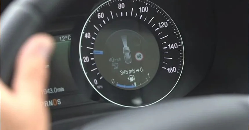
Speed limiter calibration is the process of lining up the speed governor’s internal speed calculation with a trusted reference, usually GPS or certified test gear. The goal is for the governed speed to match the legal or fleet-set limit within an agreed tolerance, so if you set 90 km/h, the truck is actually running within that window on the road, not just on paper.
Factory reset is a command, generally sent with a diagnostic laptop over a CAN bus interface, that wipes the existing configuration and sends the speed limiter back to its original default parameters. After a factory reset, the unit is basically “blank fleet-wise,” so it must be reconfigured to your standards and recalibrated before the vehicle is safe and compliant to use.
When to Calibrate vs When to Factory Reset
Most of your work as a fleet tech will be calibration, not reset. You calibrate when accuracy drifts over time, after anything that changes wheel speed vs road speed, at mileage or time intervals, or when regulations require proof that your governed speeds are still on target. You factory reset only when the firmware or parameters are clearly corrupted, you inherit a mystery configuration, or you’re bolting the limiter onto a different vehicle where the old setup no longer makes sense.
When a Calibration Is the Right Choice
In the real world, almost every routine speed limiter job is a calibration. Calibration keeps all the fleet’s policy settings, passwords, and logging behavior intact. You’re only adjusting how the device interprets the speed signal so its math matches what the vehicle is actually doing.
Typical triggers for a speed limiter calibration procedure include:
- Tire or wheel changes: Any change in rolling radius affects how many VSS pulses you get per kilometer. New tire size, different brand, or even heavily worn tread can shift indicated speed by a couple of km/h if you never recalibrate.
- Axle ratio or transmission changes: Swapping diffs, changing ratios, or certain transmission changes alter the relationship between drivetrain speed and actual road speed. The limiter still sees pulses, but they no longer mean the same speed without a new calibration factor.
- Speed complaints: Drivers insist the truck is “hitting the governor early” or “running way past the set limit.” If GPS or dash readings back that up, it’s time to verify with a proper calibration pass instead of guessing.
- Regulatory inspections: Some regions want a calibration certificate at fixed intervals, such as every year or every set number of kilometers. If the inspector asks for proof, you need to show more than a sticky note.
- Post-repair validation: Any time you change an ECU, repair CAN wiring, replace a speed sensor, or fix ABS wiring, it’s smart to treat that as a trigger for calibration so you know the new hardware and wiring are reading correctly.
- Periodic preventive maintenance: In a well-run operation, speed limiter calibration is scheduled as part of a larger scheduling calibration program. You’re not waiting for problems, you’re maintaining documented accuracy before anyone complains.
When a Factory Reset Is the Right Choice
A speed governor factory reset is more like a last-resort cleanup. You use it when the configuration is so messy or unknown that it’s safer to start fresh than to chase ghosts. You’re wiping away every custom parameter and going back to how the device left the factory.
Typical triggers for a factory reset procedure:
- Configuration corruption: Parameters don’t make sense, values fight each other, the limiter behaves erratically, or options are locked in ways that normal edits won’t fix. If you keep changing values and the unit still acts wrong, you may be dealing with corruption.
- Firmware misconfiguration: Someone has “tuned” or “optimized” the limits, tried to defeat the governor, or played with undocumented settings. The device might technically work but it’s out of compliance or unstable. In those cases, reset is cleaner than trying to reverse who-knows-what.
- Vehicle redeployment: You’re pulling a limiter from a 4×2 highway tractor and installing it on a 6×4 vocational truck, or moving between different wheel sizes and duty cycles. The old configuration is wrong for the new platform, so you reset and load the correct template for that truck type.
- Security breach or suspected tampering: Broken seals, inconsistent parameters, or logs that don’t line up with fleet policy are red flags. A factory reset, followed by a locked-down configuration, is your way to reassert control over that device.
- Manufacturer instruction: Sometimes an OEM service bulletin will say “perform a factory reset after this firmware update” to clear out old data structures or bugs. Ignoring that is how you end up with intermittent issues that nobody can reproduce.
Remember, a factory reset is never the final step. After the reset you must perform configuration restore after reset using a backup or standard fleet template, then complete a full recalibration and verification drive before the vehicle is returned to service, even if the truck seems fine in the yard.
Tools and Equipment Required
Trying to calibrate or reset a speed limiter without proper tools is how you turn a 1‑hour job into a full day of frustration. You need both the right electronics and some basic shop equipment to do this properly and safely.
Core tool list for calibration and reset
- Diagnostic laptop with manufacturer software that supports the exact limiter model. It must be able to enter calibration mode, read and write parameters, view live data, and execute factory reset commands without glitches.
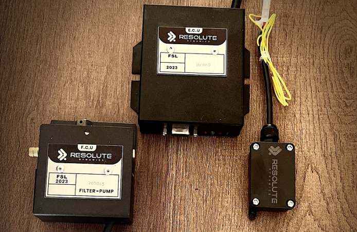
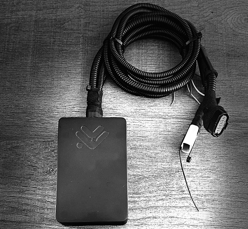
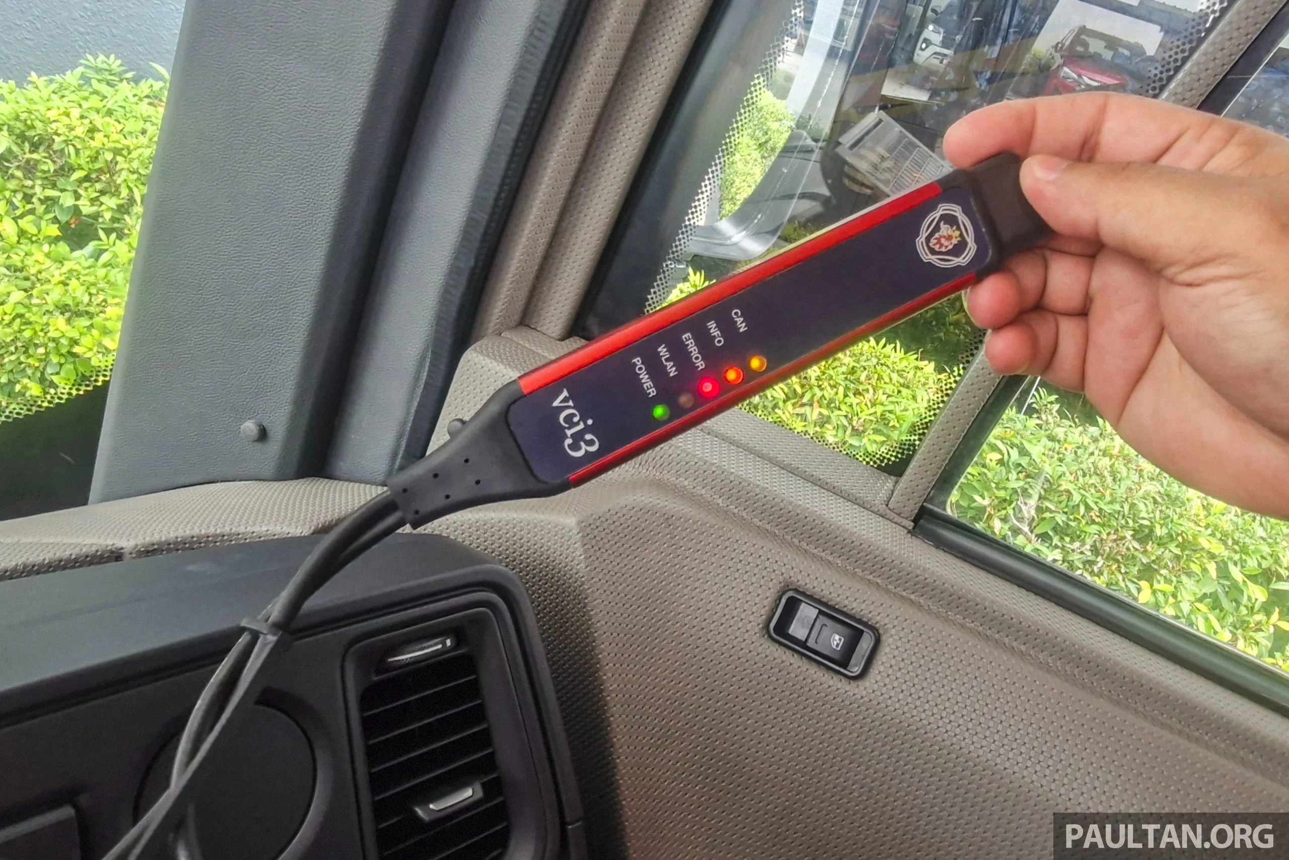
- CAN bus calibration interface (for example, a Resolute Dynamics calibration interface or similar) to link your laptop to the vehicle network. Cheap generic adapters often cause intermittent drops, which is the last thing you want in the middle of a reset.
- Speed limiter calibration tool or OEM-issued configuration dongle, where required. Some manufacturers lock advanced functions behind proprietary hardware keys, and you won’t get into calibration mode without them.
- GPS reference speed device with a known, documented accuracy, ideally in the ±0.5–1.0 km/h range. This is the heart of your GPS speed reference calibration, so don’t rely on a random phone app if your compliance depends on it.
- Multimeter to check supply voltage, grounds, and signal presence at VSS or CAN lines. If the electrical side is flaky, no amount of software tweaking will give you a solid calibration.
- Calibration certificate forms, either printed or digital templates, so you can capture all relevant parameters and test results in a format your fleet and regulators recognize.
- Tamper-proof seal kit, including wire seals, adhesive seals, and uniquely numbered labels. A sealed governor is how you prove nobody has “tuned” it since your last documented calibration.
- Torque wrench to re-torque mounting fasteners if the limiter or associated brackets get disturbed. A loose housing is not just a noise issue, it can become a failure point.
Recommended additional items:
- A stable power supply or battery support unit during programming and reset. Voltage drops during a write cycle can corrupt firmware or configuration files.
- Accurate vehicle wiring diagrams and device pinout sheets so you know exactly which wire should carry which signal before you blame the limiter for a wiring fault.
- Access to your fleet’s standard parameter sets, including governed speeds for different routes or regions, password policies, and logging preferences. Copy-pasting from a known-good template saves time and prevents human error.
- Personal protective equipment (PPE) for the road test, including a high-visibility vest, cones if you’re using a test area, and a radio or phone to coordinate with dispatch or escort vehicles.
Before you touch a truck, confirm that your diagnostic laptop software license is valid and up to date, that it covers the exact limiter firmware version, and that you have internet access if the software needs to phone home for licensing, firmware validation, or parameter database sync.
Step-by-Step Calibration Procedure
A standard speed limiter calibration procedure follows the same backbone every time: get into calibration mode, define the speed signal, set a baseline calibration factor, take the truck on a road test calibration verification run using a GPS reference, adjust for tolerance, then seal and document. Once you’ve done a few, the process becomes second nature, but you still need to stay methodical.
Enter Calibration Mode
Objective: Put the speed limiter into a controlled state where it will accept new calibration inputs without interfering with normal safety systems or throwing random faults.
Typical steps to enter calibration mode (your exact sequence may vary by manufacturer):
- Hook up your diagnostic laptop software to the vehicle using the CAN bus calibration interface such as a Resolute Dynamics calibration interface or equivalent.
- Turn the ignition to ON. Some OEMs want the engine off, others demand engine running, so follow the manual instead of guessing.
- Open the speed limiter or governing module in the diagnostic suite and log in using whatever credentials or security token the OEM requires.
- Navigate to the calibration mode, “speed governor configuration,” or equivalent menu where the speed-related parameters live.
- Check system status. Scan for active DTCs that could affect speed readings, like ABS faults, VSS issues, or power supply errors, before you even think about changing values.
Technician tip: Before you touch a single parameter, run a full parameter backup before reset or calibration. Export the current configuration to a file and name it with the VIN, date, and odometer. Too many techs skip this step and regret it later when they realize they overwrote a special configuration they can’t recreate from memory.
Configure the Speed Signal
Objective: Tell the speed limiter exactly where it should get its speed information from and set the initial calibration factor so its math matches your hardware.
Most speed limiters can take speed from one or more of these sources:
- VSS (Vehicle Speed Sensor) that produces a pulse train, often from a Hall-effect sensor mounted on the transmission or differential. The unit translates “pulses per wheel rotation” into speed.
- CAN bus speed provided through a specific CAN PID speed source or PGN message from the engine ECU, transmission, or ABS system. In many modern trucks this is the primary source.
- GPS speed, which is not usually used as the main control input but is very useful as a cross-check against CAN or VSS.
Key calibration factor elements (EAV coverage):
- VSS pulses per km: The conversion factor between sensor pulses and a distance of 1 km. A common starting point might be 10,000 pulses/km, but that number shifts when tire size or gearing changes.
- CAN PID speed source (ID): The CAN ID or PGN where the limiter should listen for speed. Pick the wrong one and you’ll calibrate to the wrong signal entirely.
- GPS reference accuracy (± km/h): Your GPS tool should clearly state its accuracy, typically in the ±0.5–1.0 km/h range. If you don’t know the device’s accuracy, you can’t honestly claim tight calibration.
- Tolerance acceptable (± km/h): The legal or policy window around the set speed, for example ±2 km/h. That defines your pass/fail band.
- Recalibration trigger: Documented rules like “after any tire change,” “every 50,000 km,” or “every 12 months,” which help standardize how often you revisit these settings.
Configuration steps:
- In the diagnostic tool, choose the correct speed signal source for that vehicle: VSS, CAN, or a defined combination, following the OEM recommendation.
- Enter or confirm the calibration factor. For VSS, that’s the pulses per km. For CAN, it’s usually a matter of confirming the proper CAN PID and ensuring no scaling errors are present.
- Cross-check what you see against your fleet standards or OEM baseline. If the truck just got new tires or a ratio swap, update the factor so it reflects the new mechanical setup.
- Save your changes, but stay in calibration mode and keep the laptop connected until you complete the road test and any fine tuning.
Road Test Verification
Objective: Prove that the speed limiter’s internal speed matches a trusted GPS reference speed across the operating range, not just at one single point.
Pick a safe, repeatable road test route that meets these criteria:
- Straight and level pavement so grades and curves don’t constantly change load and speed.
- Light to moderate traffic where you can hold a steady speed without constant braking or lane changes.
- Legal speed limits that allow you to reach the governed speed you’re targeting without breaking the law.
Road test verification (EAV coverage):
- Test speeds (km/h list): Use several clear points such as 40, 60, 80, and then the governed speed, whether that’s 90, 100, or another policy value.
- Governed speed tolerance (± km/h): For example, if governed speed is 90 km/h, your tolerance might require that the truck never exceed 92 km/h and doesn’t start limiting earlier than 88 km/h.
- GPS cross-check method: Watch GPS speed alongside the limiter or CAN-reported speed on your laptop at the same time. Don’t rely on one reading you saw for a moment.
- Test route requirements: Use a known route that technicians can repeat so your results are comparable across the fleet.
- Duration per speed point (seconds): Hold each test speed for at least 20–30 seconds, so both GPS and the limiter’s calculated speed have time to stabilize and any lag settles out.
Example road test sequence:
- Stabilize at 40 km/h using GPS as your guide. Record the limiter’s calculated speed from your laptop and note the difference.
- Repeat the same process at 60 km/h and again at 80 km/h, writing down GPS and limiter values each time.
- Ease the truck up toward the governed speed. Watch the GPS and record the exact speed where the limiter begins to hold or cut power.
- Log all of these readings in your calibration worksheet so you can later attach them to the calibration certificate as hard evidence.
Calibration Tolerance Check and Fine Adjustment
Objective: Tweak the calibration factor so the limiter’s reading and actual GPS speed fall within your defined calibration tolerance, with special focus on behavior at the governed speed.
Compare each data point against your tolerance band:
- If GPS shows 90 km/h and the limiter reports 88 km/h, you’re sitting at -2 km/h. That may be acceptable for many regulations, but always confirm what your jurisdiction and fleet policy demand.
- If GPS shows 90 km/h but the limiter allows the vehicle to hit 95 km/h before it clamps down, you’re +5 km/h. That’s usually a fail, and you must correct it before the truck goes back into regular service.
Use the diagnostic tool to adjust and verify:
- Change the calibration factor in small steps, typically 1–2% at a time. Huge jumps usually mean you misdiagnosed the issue or picked the wrong speed source.
- Prioritize getting the governed speed dead on within the tolerance acceptable (± km/h) from law or company policy. That’s where enforcement will pay the most attention.
- Once the top end is dialed in, confirm that the intermediate speeds are still within a reasonable deviation. Some small non-linearity is normal, but large swings mean something else is wrong.
Expert tip #1 (often missed): Always record both the new calibration factor and the old factor you replaced. Over the years, that history helps you spot patterns, prove that you didn’t “open up” speeds illegally, and troubleshoot future complaints.
Expert tip #2: If the CAN-reported speed and GPS are way off, don’t just fudge the limiter to match bad data. Go back and inspect wheel speed sensor scaling, ABS configuration, or ECU settings. Calibrating around a faulty speed source is just hiding the real problem.
Seal & Document
Objective: Lock in the configuration so it’s tamper-evident and fully traceable by applying tamper-proof seals and updating all calibration log documentation and certificates.
Tamper-proof seal application (EAV coverage)
- Seal type: Common options are wire seals threaded through mounting hardware or adhesive seals placed across covers or connectors that clearly break if disturbed.
- Application point: Place seals across the limiter’s enclosure screws, main harness connectors, or any adjustment covers that someone might open to defeat controls.
- Seal number recording: Every seal has a unique number. Record each one on the calibration certificate and in your workshop log. Inspectors often write those numbers down during roadside checks.
- Inspection verification: During periodic inspections or internal audits, verify visually that the seal is intact. Some fleets also take date-stamped photos or use RFID-tagged seals for higher security.
- Replacement requirement: Any time you remove a seal for legitimate service, you must cut it, do your work, then install a fresh seal and record the new number. Reusing a broken seal defeats the purpose.
On the paperwork side, finish your documentation while the details are still fresh:
- Update the calibration log with date, VIN, plate, odometer, technician name, tools used, and key parameters such as governed speed and calibration factor.
- Create a calibration certificate for that job, following your standard format. Keep at least one copy in the shop records and one in the fleet office or digital management system.
- Note any unusual conditions, such as temporary test routes, borderline readings that still passed, or follow-up checks scheduled for later.
If your company runs a structured post-calibration audit, make sure your paperwork lines up with their checklist. Missing data points during an audit often matter more than the actual speeds you achieved.
Step-by-Step Factory Reset Procedure
A solid factory reset procedure follows the same pattern every time: make a complete backup of the existing configuration, perform the reset with the proper command, confirm that parameters returned to defaults, reload a valid fleet configuration or template, and run the full calibration and verification drive before handing the keys back. Skipping any of those steps is asking for trouble.
Backup Configuration
Objective: Protect yourself and the fleet so you can put the truck back exactly how you found it if anything goes sideways during reset or reprogramming.
- Connect your diagnostic laptop and CAN bus calibration interface to the truck and confirm you can communicate with the limiter module.
- Read out every relevant parameter: governed speeds, speed source configuration, calibration factors, passwords, logging and event settings, and any custom fleet options.
- Export these settings to a configuration file. Use a naming convention that includes VIN, date, technician ID, and “as-found” so you know what it represents later.
- Store the backup in your fleet’s central repository or configuration management system where it won’t get lost on someone’s desktop.
Expert tip #3: Always keep two snapshots: an “as-found” backup before you change anything, and an “as-left” backup after you’ve completed calibration and verification. If there’s ever an incident or warranty claim, those two files help prove what was done and when.
Execute Reset
Objective: Cleanly return the speed limiter to factory defaults using the approved method so you’re not left with half-cleared data or partial settings.
Factory reset (EAV coverage)
- Reset method: In most systems this is a “factory reset” or “restore defaults” option in the OEM diagnostic tool. Some units also require a specific hardware jumper, pin bridge, or ignition cycle sequence to confirm the reset.
- Data erased: Expect configuration data to vanish. In some models, trip logs and historical events are also cleared. Always check the OEM documentation if those logs matter to your compliance program.
- Backup required: Treat backup as mandatory, no exceptions. If you skip this and the reset exposes a hidden firmware issue, you may not be able to recover.
- Restore time: Budget 5–20 minutes for a full reset and reconfigure cycle on most platforms, longer if you’re dealing with complex multi-module setups.
- Post-reset requirement: You must recalibrate speed and governance parameters, then confirm behavior with a road test before putting the truck back into regular duty.
Execution steps:
- Set the ignition state exactly as specified by the OEM. Wrong ignition state can sometimes block or corrupt the reset process.
- Run the factory reset procedure command from your diagnostic software and confirm the tool acknowledges the command.
- Let the process run to completion. Don’t disconnect the CAN bus calibration interface, don’t close the laptop, and don’t cycle power halfway through.
- Follow any instructions from the tool or service manual to cycle ignition or reboot modules, then reconnect and verify communication.
Reload & Recalibrate
Objective: Put the limiter back into a known, compliant state with the right fleet parameters and verified speed control.
- After reconnecting, check that parameters such as governed speed, speed source, calibration factor, and passwords are now at OEM defaults. If they’re not, repeat or investigate the reset process.
- Perform the configuration restore after reset using:
- The backup file you saved earlier, if this limiter is staying on the same vehicle with the same policy, or
- Your standard fleet template for that vehicle class if you’re redeploying the limiter or fixing a badly misconfigured unit.
- Double-check all key policy values: governed speeds for each mode, access control, logging options, and any regional settings that tie into compliance.
- Run through the full speed governor calibration steps covered earlier: re-enter calibration mode, validate the speed source, set the calibration factor, and carry out road tests with tolerance checks.
- Finish with a proper post-calibration verification drive and build updated documentation, including new seal numbers and a fresh calibration certificate.
Once that’s done, apply new tamper seals over any access points and update your logs to clearly state that a factory reset plus recalibration were completed on that date and mileage. Those details often make the difference in warranty and liability discussions.
Post-Calibration Verification and Documentation
Many techs think they’re done as soon as the laptop shows no errors. That’s only half the job. Post-calibration work means proving in real-world use that the limiter behaves correctly, then building a paper (or digital) trail that you can rely on in an audit or investigation.
Post-Calibration Verification Drive
Objective: Verify that in real driving, just below and at the governed speed, the limiter operates exactly how you intended, with no surprises or surging.
A typical road test calibration verification protocol after your final adjustments looks like this:
- Drive at 10 km/h below governed speed, for example 80 km/h if the truck is governed at 90:
- Confirm there’s no limiter intervention. The truck should feel normal at that speed.
- Compare dash speed and GPS reading. Small differences are fine, but anything large should push you to recheck calibration or cluster settings.
- Drive steadily at the governed speed:
- Watch how the limiter holds speed. It should be smooth, not cycling on and off aggressively.
- Record the GPS speed at the exact point where the limiter holds or begins to trim power.
- Try to push about 10 km/h above the governed speed, only where it’s safe and legal:
- Confirm the limiter prevents the truck from maintaining that higher speed. Short bursts may still be possible, but the system should pull it back in line.
During that same drive, keep an eye on:
- GPS reference speed as your independent yardstick. If the GPS is jumping around, the data’s no good, so pick a more stable stretch or better device.
- CAN data output on the diagnostic laptop. Compare ECU-reported speed to GPS and what the limiter believes. They should all be in the same ballpark.
- Any new fault codes that appear only under load or at highway speeds, which may indicate wiring or sensor issues you didn’t see in the bay.
Calibration Certificate Generation
Objective: Produce a formal record that shows not just that you worked on the limiter, but that you verified it was within tolerance according to your fleet policy and regional requirements.
Calibration certificate (EAV coverage)
- Data recorded:
- Date and time the calibration was completed, not just when the work order was opened.
- Vehicle identifiers: VIN, make, model, and registration number so there’s no doubt about which unit the certificate covers.
- Odometer reading at the time of calibration, which helps track intervals and supports maintenance schedules.
- Name and ID of the technician who performed the work, plus fleet technician certification details if your operation or region relies on certified personnel.
- Key configuration parameters like governed speed, selected speed signal source, and the final calibration factor you settled on.
- Road test data, including test speeds, GPS readings, limiter readings, and the results of your tolerance check at each point.
- Signature requirement: Most structured fleets and many regulators require a technician signature, physical or digital. Some companies also mandate a supervisor or quality manager sign off for extra assurance.
- Validity period: Certificates typically carry a validity window such as 12 months or a specific mileage. Always match this to local rules and your own fleet standards.
- Regulatory submission: Roadside inspectors and auditors can ask for these records. In some jurisdictions you may need to submit them proactively during compliance audits.
- Digital vs paper: Many fleets are shifting toward digital certificates stored in their fleet management systems. Paper copies are often still printed and placed in vehicle files or given to drivers when crossing into stricter regions.
Log Updates and Record-Keeping
Beyond the certificate, every vehicle should have a running calibration log. That log shows the history of changes, not just the last event, which is valuable when regulators or insurers look back several years.
- For each event, record:
- Date, time, VIN, technician, and work order reference so every entry ties back to actual documented work.
- Whether the job was routine preventive calibration, post-repair verification, or part of a structured post-calibration audit.
- All seal numbers installed and removed, including any reason seals had to be broken.
- Any variations from standard procedure, such as alternative test routes or temporary limits set for a specific contract.
- Link each calibration entry to inspection reports, driver complaints, or incident records where relevant so you can reconstruct timelines later.
For specialized units such as school buses or other high-liability passenger vehicles, always follow your dedicated guidance on school bus calibration intervals and documentation. These vehicles often run under tighter rules than general freight units.
Common Mistakes Technicians Make (and How to Avoid Them)
- Skipping the backup before reset: This is one of the most painful mistakes. Without a configuration backup, you can easily lose custom fleet settings that took years to standardize. Always export the “as-found” settings before you touch anything, even if you think you’re only doing a simple calibration.
- Calibrating against an unreliable speed source: Trying to calibrate on a steep grade, in heavy traffic, or with a cheap GPS that keeps dropping satellites is a waste of time. You’ll lock in bad data. Use a solid GPS device and a proper test route where speeds can stabilize.
- Ignoring intermediate speeds: Focusing only on the governed speed can hide non-linear issues or scaling errors. Always check several points like 40, 60, and 80 km/h plus the limit. That’s where you’ll spot odd behavior that might come back as a driver complaint later.
- Failing to reapply tamper seals: Leaving a limiter unsealed after calibration is like leaving a safe open. You have no way to prove that nobody changed anything after you left. Treat tamper-proof seals as part of the job, not an optional extra. For more detailed sealing practice, follow your internal or external guidance on tamper seals.
- Not documenting tolerance results: Writing “OK” in the log gives you nothing to stand on during an inspection. Record actual measured speeds and deviations so you can demonstrate that the limiter met your defined tolerances on the day you worked on it.
- Using outdated configuration templates: Reusing an old config file that no longer matches legal limits or company policy is more common than people admit. Make sure your templates and standard parameter sets are reviewed and updated whenever laws or company rules change.
- Mixing up calibration and troubleshooting: If a limiter doesn’t engage, surges badly, or behaves unpredictably, don’t keep recalibrating in hope it magically fixes itself. Diagnose the underlying electrical, sensor, or firmware fault first, then calibrate once the system is healthy.
Companion guides: Post-installation audit checklist – Handling tamper-proof seals – Troubleshooting RPM inconsistencies.
FAQ: Calibration and Reset for Speed Limiters
This FAQ tackles real questions that come up in shops all the time, including calibration time, technician certification, out-of-tolerance units, warranty concerns around resets, and typical costs of speed limiter calibration tools.
How long does it take to calibrate a speed limiter device?
On a platform you know well, a full calibration that includes connection, parameter review, road testing, tolerance adjustments, and final documentation generally runs about 45–90 minutes per vehicle. Expect extra time if you uncover wiring problems, have to run multiple test loops because of traffic, or need to coordinate with operations for access to a specific route.
Do I need to be certified to perform speed limiter calibration?
In some regions, only technicians with specific fleet technician certification or OEM training are allowed to sign off on speed limiter work. Even in places without that legal requirement, having documented training on these systems protects both the company and you, especially if your name is on the certificate that regulators review later.
What happens if the limiter cannot be calibrated within tolerance?
If after careful adjustment the limiter still fails the required calibration tolerance check, treat the unit as faulty. You need to dig into the speed source itself, whether that’s the VSS, ABS pickups, CAN configuration, wiring, or even internal limiter hardware. The safe option is to limit the truck’s operation or keep it out of service until you can fix the root cause and pass a full verification.
Does performing a factory reset affect the device warranty?
Using the official factory reset procedure with approved diagnostic tools rarely affects warranty on its own. In fact, manufacturers often recommend it as part of troubleshooting. Where you run into trouble is using hacked tools, modifying firmware outside OEM guidance, or bypassing security. Always follow the manufacturer’s instructions and log each reset event in case a warranty claim comes up later.
What do speed limiter calibration tools and software typically cost?
There’s a wide range. A reliable CAN bus calibration interface and OEM laptop software typically starts in the low four-figure range for a single-brand solution. Multi-brand, dealer-level or fleet-level suites can climb much higher, especially once you include yearly license renewals, firmware subscriptions, and support contracts in your budget.
How often should we recalibrate our fleet’s speed limiters?
For most fleets, recalibrating once per year or every 50,000–80,000 km is a sensible baseline, as long as you also recalibrate after tire size changes, axle ratio swaps, ECU replacements, or any major work involving speed sensors and wiring. For broader planning and policy-level decisions, lean on your separate guidance on scheduling calibration.
Is a post-calibration verification drive always required?
Yes, if you want to be confident in your work. A yard-only or static calibration without road test calibration verification leaves you guessing how the limiter behaves under real load and traffic conditions. Even if you sometimes use a chassis dyno, you still need to confirm behavior at and around governed speed before you hand the vehicle back.
Can I rely solely on CAN speed without GPS cross-check?
You can technically calibrate against CAN speed alone, and some operations do that, but using GPS speed reference calibration gives you an independent check that’s hard to argue with during audits. Whenever possible, confirm that CAN speed and GPS readings line up within your defined tolerance, then document that agreement.
Final Summary and Next Steps
Accurate speed limiter calibration and smart, controlled use of factory reset are non-negotiable for any modern fleet that wants to stay safe, compliant, and legally protected. With the right speed limiter calibration tools, a repeatable process, and solid documentation, you can be confident that the governed speeds on your trucks match fleet policy and legal requirements within a tight, verifiable tolerance.
Use this guide as your hands-on reference on the shop floor whenever you calibrate or reset speed limiters, and connect it with your internal playbooks for scheduling calibration, post-calibration audit, and tamper seal management. That combination turns one-off jobs into a consistent, auditable program that stands up under scrutiny.
Before your next job, take a few minutes to inventory your tools, confirm your diagnostic laptop software access, and make sure your calibration templates and certificate forms match current policy. That prep work is what keeps each calibration consistent, efficient, and fully defensible if anyone ever questions how that vehicle was governed.

The Resolute Dynamics team designs and manufactures speed limiters (SLD), GPS tracking, and automotive safety systems used on 200,000+ vehicles across 20+ countries. We write about fleet compliance, road-safety regulation, and vehicle-safety technology, including Malaysia’s JPJ SLD mandate, UAE RTA rules, and global standards like UN R89, to help fleet operators and transport businesses stay safe and compliant.